Got an interesting repair in. An A-B-A that has two powered A-units, each with a K-Line cruise board. Of course, you have figured out the story, the trailing A has fried it's cruise board! OOPS, there are no replacements for those.
The logical replacement is an ERR Cruise Commander M, but the speed curves will be totally different, so that's probably going to be a significant issue. The K-Line cruise and ERR cruise do not play well together. So, I figure to replace both the working and non-working K-Line cruise boards. Each unit will get a Cruise Commander M board.
Now comes the fly in the ointment...
The K-Line cruise boards just use serial data, but the CC-M wants serial data, the two PWM direction outputs, and the +5V DC from the R2LC! That's three extra pins! That could get ugly! I examined the K-Line cruise 1--pin tether, and to my amazement there are four ground wires out of the ten pins! They have separate grounds for the coupler, lights, smoke, and the standard frame ground! I just found my three wires! ![]()
Next up is the issue of driving two motor control boards from the R2LC PWM outputs, it doesn't have the drive to get it done. Each motor control board has a set of opto-couplers to receive the PWM data, paralleling them causes all sorts of issues. The serial data is also marginal, especially after it travels through a few tether connections to the trailing unit.
I've actually run across this before, but this time I decided that I should consider a way to do multiple powered units without having totally separate electronics. I suspect this isn't the last time I'll see this same configuration.
Time to fire up the Circuit Board Design tools. ![]()
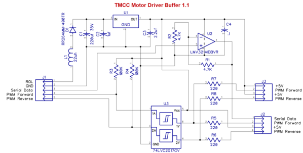
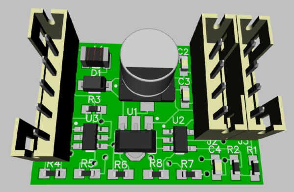
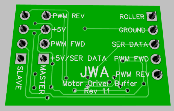
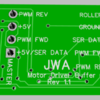
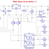
This is a board that will allow me to boost the serial data for the long trip to the rear, and also provides two buffered outputs for the PWM drive from the R2LC. The buffer has sufficient drive to power three or four opto-couplers, two won't be a challenge. This board will feed both the lead A unit CC-M and the trailing A unit CC-M with buffered PSM inputs. The independent 5V power supply will also prevent us from overloading the R2LC 5V power output since it has very limited capability.
This board (when it comes back from OSHPark) will provide the buffering to tie these units together for proper operation.


