A few questions so I understand where you are and where you want to go.
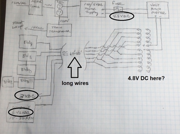
1. Your photo shows what appears to be a bundle of twisted-pair cables from panel to shelf. It looks like maybe AWG 24 wiring?
2. By having multiple (you show 5 in diagram above) pairs of "long wires," is your ultimate objective to have (up to) 5 shelf accessories turning ON and OFF independently and at different times?
3. You have 4.8V DC at the panel. I don't understand how you "adjust" the voltage up at the accessories? Are you depending on the voltage drop in the long runs of wire (~150 feet round-trip) as the sole-method of reducing the 4.8V down to 3V (or whatever)? Or are there other components on the shelf (such as resistors) other than LEDs?
4. You show a 3V DC output on the shelf with nothing connected (no building, no windmill). Presumably this was measured with a meter? If using a meter as the only "load" on the 2-wire cable that started at 4.8V DC, even after 80 feet it is essentially inconceivable that the voltage would drop to 3V.
5. The windmill is labeled 6-12VDC. Is this "just" connected to one pair to the panel...and then the voltage is what it is? That is, it will be something less than 4.8V DC depending on the drop from the long run of wiring. Is this what you want or do you really want control over the windmill RPM?
6. Finally, you mention a "simple" solution. How does "simple" translate into budget? Are we talking $10 or $100 or ?? And by "simple" does this mean soldering is off the table?


