@Dusty Tumbleweed posted:..The "mangled English translations" is one of the problems that i have had in the past when trying to figure out these micro controllers.
So looking and reading about the different delay timers for sale I came across one of these and had a thought. (don't say it, yes I'm having trouble seeing through all the smoke)
With these Asian-designed chips/modules, I've found it worth the time to try to find what I call the mother document...typically in Chinese. From what I can tell, all the eBay, and even Amazon, sellers simply copy each other's mangled English...in some cases mangling the instructions even more until it's almost comical to read. ![]()
I am not familiar with the chip you refer, but for 15 cents I'll take the bait.
Sometimes you can find what might be the mothership of documentation and there may be some tidbits to be gleaned even without Chinese language skills. Or, look for someone who has taken it on as a personal mission to figure it out...kind of like how I'm slowly unraveling the mysteries of the multifunction timer relay module.
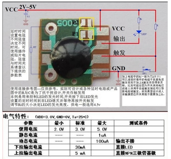
I found this well-written (English) description by some kindred spirit. My browser says it's not a secure website so be advised - I won't make it a click-able link but it was full of useful info:
http://westsideelectronics.com/delay-timer-ic/
Anyway, from what I learned this would be classified as a "delay-OFF" timer. In other words, you apply power...the output immediately turns ON...the delay interval completes...and the output turns OFF. So this is not what you want.
As I understand it, you want a "delay-ON" timer. In other words, you apply power...the output remains OFF...the delay interval completes...and the output then turns ON and stays ON.
I did not look to see if there are 15-cent "delay-ON" timer modules. That is, if I had them in hand I'd just tack on some cheap components to do what you want:
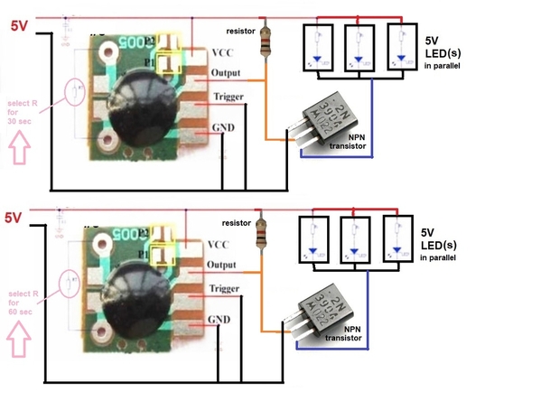
For example, with the addition of a 5-cent resistor and a 10-cent transistor you can "invert" the output of the 15 cent module so that the LED(s) would turn ON some settable delay after 5V power is applied to the module. Obviously we are entering the realm of soldering tiny components so it's not in everyone's comfort zone. So in the diagram above, let's say the timing resistor on the left is chosen for 30 sec for the upper module and 60 sec for the lower module.
Then, when 5V power is applied at 6pm by the Intermatic timer, the upper module's 5V LEDs would turn on AFTER a delay of 30 sec. The lower module's 5V LEDs would turn on AFTER a delay of 60 sec. More modules can be added.


