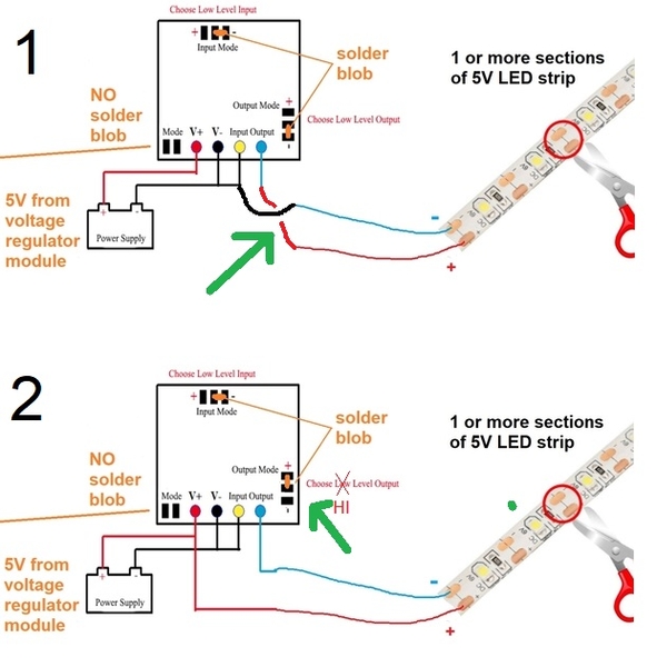
In the absence of better information on exactly what the module does, and realizing you are not excited about experimentation, I nevertheless suggest two experiments:
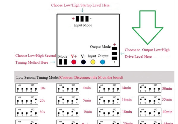
I suggest this after trying to interpret the solder blob for OUTPUT mode. You apparently get to select either + or - Output Drive Level.
I assume the Output blob is presently in the Low or "-" position.
Experiment 1. With Output blob in the Low position, re-connect the LED wires as shown pointed to by Green arrow.
Experiment 2. With LED wires back to original position, move the Output blob (pointed to by Green arrow) to the High position.
Given translation difficulties it's hard to say for sure what they mean by High and Low output drive level. But I can't imagine the purpose of an Output Level selector blob if not to change between Delay-OFF to Delay-ON or provide some form of signal inversion.
If neither of these work, then I suppose an external transistor could be used to invert the logic. If something like a 2N3904 is in the cards, the external circuit can be designed to work with 5V or 12V LED strips.
BTW, I also ordered a few of these modules to mess with albeit maybe a week after you. So if you don't want to experiment, hopefully I'll get mine next week and I'll get this timer module issue sorted out. I figure you must have hours upon hours of work to install/retrofit the LED strips into your buildings...


