Thank you for the reply.
Oh boy we are having fun now. Tried some experimenting today. 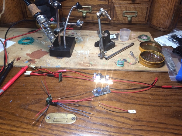 Here is one wired like the original diagram. Power on = LED lit - off after 10 sec. Another one getting ready to experiment with.
I soldered some wires to the blob spots to make changes quicker and easier. 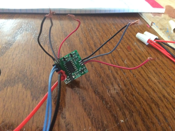
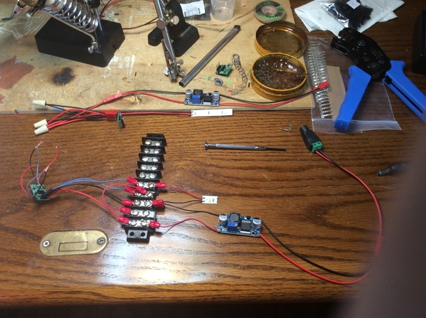 Also added some connectors and a terminal strip to aid in wire changes.
Seems you are right about inverting the output. I did get a delayed on on three different configurations. But the LED was dim.
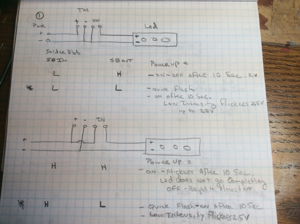
Results for experiment 1.
Power up = what happens when power is applied.
Solder blob =SB.
SB IN - I am guessing refers to the trigger for the output.
SB OUT- seem to be if the output will be high or low.
Experiment 2 and variation.
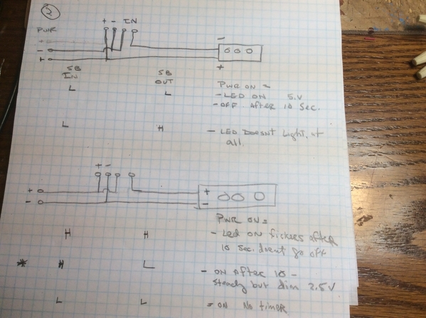 A little closer but still not winning. Maybe I’ll try a little more later tonight.


