Stan, no worries if this TD module is not correct for my application. All is not lost. I’ve learned a lot. This has been an interesting thread.
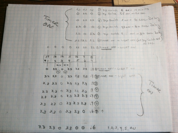
So I was giving this some thought. If one pin on the micro controller had a pin for delay off maybe there is one for delay on. Sort of a common, normally open, normally closed function. Maybe I could find a pin out for the chip. No such luck. No part number on it. So the next best thing would be to see what I could. Found the pin that drives the output. Pin #1. I could also see the brief flash on power up on my meter. Had to dust off the old analog meter to catch it. During the timer cycle pin 1 is 3.3v. After time out it goes to 0. Your boot up theory seems correct. Since I was already fooling around with it I went thru the other pins. 5,6,8,9,10 I believe are the dip switch inputs. Shorting pin 3 to 4 turns the light on. Guess how I figured that out.![]() I believe 2 and 3 are + and -. 7 the voltage is not always constant. Don’t know what going on there. 11 thru 14 never have anything on them. Anyhow that’s what I see fooling around with my meter.
I believe 2 and 3 are + and -. 7 the voltage is not always constant. Don’t know what going on there. 11 thru 14 never have anything on them. Anyhow that’s what I see fooling around with my meter.


