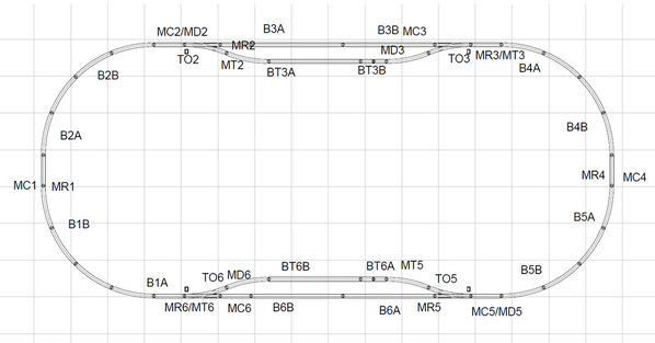
An oval test track was designed to test all the Lay Command and Control, LCC, signal and automation electronics and software before starting a much larger layout. Layout Command Control, LCC, is a NMRA standard protocol for layout automation. This is a link to several presentations http://www.rr-cirkits.com/Clinics/Clinics.html. This is a link to NMRA LCC documentation https://openlcb.org. This is a link to an LCC discussion group https://groups.io/g/layoutcommandcontrol/topics. Dana Zimmerli authored Introduction to Layout Command Control: Basic Concepts and Practical Examples of LCC for Model Railroads. Train Controller Gold is the automation software. (It was chosen after discussions with a professional model train layout designer and installer.) The oval test track with sidings as shown in Fig. 1.
Fig,1. LCC signal, block detection and Train Controller automation test track.
Definitions:
B-Block, example: B”1”-Block 1, B1”A”-Block 1 detection section A.
M-Signal Mast, M”C”-Clockwize signal, M”R”-Reverse Clockwise signal, M”D”- Clockwise Turnout signal, M”T”-Reverse Clockwise Turnout Signal, example: MC”1”- Clockwise signal Block 1.
TO-Turnout, example: TO”2”-Turnout Block “2”.
I described my layout vision here https://ogrforum.ogaugerr.com/...69#81819043117203669. It will take 4-8 months to complete all the hardware and software development. It will be easier to describe and document the work along the way.
The design choices were made taking cost, technical capabilities, my time and the joy of learning into account. Even before the test track was built a simulator of the test track was built and tested. The test simulator will be described in this topic. The test track uses a basic Automatic Block Signaling, ABS, system. Three aspect masts are used on the mainlines. The red stop aspect indicates that the next block is obstructed, yellow approach speed aspect indicates an obstruction in the block after the next and the green clear speed aspect indicates no obstruction to be expected. Two aspect masts are used for the siding. The red stop aspect indicates the siding is obstructed and the yellow approach speed aspect means proceed onto the siding or off the siding onto the mainline. The LCC logic is capable of implementing very complex block signaling systems. Several HO layouts have implemented more complex signaling of the railroad they are modeling. The LCC network contained three RR-CirKits Signal LCC nodes, RR-Cirkits LCC-LocoNet Gateway, RR-Cirkits LocoNet USB Buffer, RR-Cirkits Power-Point (May have trademark problems ![]() ), my design ESP32 LCC 18-Input node and my design ESP32 LCC 16-Output node. My ESP32 LCC nodes with MRNLite open source software are about 84% less per simple I/O than RR-CirKits. The RR-CirKits nodes are used for the infrastructure and the more complex logic needed for track signals. The ESP32 LCC 18- Input and ESP32 LCC 16-Output are shown in Fig 2.
), my design ESP32 LCC 18-Input node and my design ESP32 LCC 16-Output node. My ESP32 LCC nodes with MRNLite open source software are about 84% less per simple I/O than RR-CirKits. The RR-CirKits nodes are used for the infrastructure and the more complex logic needed for track signals. The ESP32 LCC 18- Input and ESP32 LCC 16-Output are shown in Fig 2.
Fig. 2 ESP32 LCC 18-Input and ESP32 LCC 16-Out are on the Left and Right respectively.
The LCC network is implemented using the CAN bus over ethernet cabling. The ESP32 LCC 18-Input is shown with three 6-channel block occupancy detectors (3-rail) in Fig 3. The 6-channel block occupancy detectors are based on a design by Professor Chaos, https://ogrforum.ogaugerr.com/...29#69425981478787229.
Fig. 3 ESP32 LCC 18-Input node connected to 3 6-channel block occupancy detectors.
The RR-CirKits LCC Signal Nodes, RR-Cirkits LCC-LocoNet Gateway, RR-Cirkits LocoNet USB Buffer, RR-Cirkits Power-Point are shown in Fig 4. The LCC-LocoNet Gateway and LocoNet USB Buffer are required to communicate with Train Controller. Only a USB-LCC Buffer is required to communicate with JMRI or stand alone.
Fig. 4 RR-CirKits LCC Signal, LCC-LocoNet Gateway, LocoNet USB Buffer and Power-Point.
To reduce cost a 3 aspect mast LED driver board was designed to use only the red and green outputs from the RR-CirKit LCC Signal node to generate the yellow output (When there is no red or green output a yellow output is generated). A CMOS 4 channel 3 aspect mast LED driver board is shown in Fig 5. A TTL version was also developed.

Fig 5. A 4 channel 3 aspect mast LED driver board (CMOS version)
A red or green aspect signal generated by the RR-CirKits LCC Signal node costs about $4 and a yellow aspect signal generated from the red and green signals cost about $0.50. To reduce cost a 2 aspect mast LED driver board was designed to use only the red output from the RR-CirKit LCC Signal node to generate the yellow output (When there is no red output a yellow output is generated). The CMOS 8 channel 2 aspect mast LED driver board is shown in Fig 6. A TTL version was also developed.
Fig 6. A CMOS 8 channel 2 aspect mast LED driver board
All the components used in the test track simulation before wiring are shown in Fig 7. The RR-CirKits LCC-USB Buffer is shown instead of the LCC-LocoNet Gateway and LocoNet USB Buffer. There are 3 sets of slide switches to emulate track section occupancy. There are 3 boards with LEDs simulating the 12 x 3 aspect masts, a board with LEDs simulating the 8 x 2 aspect masts and a board with LEDs simulating the position of the turnouts. A push button board is used to set the position of the turnouts.
Fig 7. The test track electronic components.
The wired test track simulator with no mainline obstructions is shown in Fig 8.
Fig 8. Wired test track simulator with no mainline obstructions.
Unfortunately, the red LEDs look yellow to my iPhone. Figures 9a, 9b, 9c and 9d show the labeled slide switches for block occupancy, LED boards for the 12 x 3 aspect masts, the LED board for the 8 x 2 aspect masts and LED board for the turnout position and the push button turnout control board, respectively.
Fig 9a. Block occupancy slide switches
Fig 9b. 12 x 3 aspect mast LEDs
Fig 9c. 8 x 2 aspect mast LEDs

Fig 9d. 4 push button turnout controllers.
Video 1 shows test track simulator (repeat of the photos)
Video 1. The test track simulator
Video 2 shows the test track simulator when different turnouts are thrown.
Video 2. Turnouts changing on the test track simulator.
Video 3 shows the test track simulator with various block occupancies and turnout positions.
Video 3. Test track simulating block occupancies.
The LCC test track simulator worked correctly for all the different configurations tested. LCC can be the lowest cost, most flexible and largest scalable block signal system available to model train layout hobbyists. Later this week, grandkids permitting, I will continue the post showing videos of Train Controller working with the LCC test track simulator and TMCC. When I return from the lake I will build Professor Chaos’s Legacy to DCS Bridge and use it with Train Controller, https://ogrforum.ogaugerr.com/...ote-proof-of-concept. This will allow the Train Controller to automate both TMCC and DCS engines. I will also post the incremental cost per mast calculation. My initial cost goal was $5 but the use of the RR-CirKits LCC Signal nodes raised the goal to $12 per mast. (I didn’t want to develop and test the complex signal logic. A my time versus cost decision.)


