This post will describe how to build a simple interface between the Lionel LCS system and the MTH TIU. With the impending demise of the MTH DCS remote, I thought there might be interest in running PS2 or PS3 trains with the Lionel Legacy remote.
To cut to the chase, I haven't developed a full system for running DCS with the CAB-2 and don't plan to do so. What I've created is the necessary hardware, and provided a basic software framework for reading Legacy commands from the PDI bus and sending a corresponding command to the TIU. My hope is that this project will enable other people who are interested to pick up where I've left off, and further develop the software side!
This project was an offshoot of my DIY TMCC remote control, which used an RFM69 radio module to transmit commands received over the Lionel LCS bus to control operating cars. @SanDiegoMark has done amazing work reverse-engineering the radio communication between the DCS remote and the TIU and showing how to write your own software to control DCS engines. When Mark extended his system to use the RFM69 radio module, I decided to build a bridge module that would read Legacy commands from the CAB-2 and control a DCS engine based on that input.
While it’s possible to read commands from the TMCC or Legacy base serial port, doing so may require additional hardware such as a SER2 module. Moreover, because the TMCC and Legacy command bases use earth ground as the reference for the serial bus, a separate power supply or optical isolation is necessary to avoid shorting layout common to earth ground (which may interfere with the TMCC signal). Instead, this system plugs into the Lionel LCS PDI bus, and is powered directly from the 12v line on the PDI bus. The total cost of the interface hardware is about $30, including the custom PCB.
Basic Hardware:
Mark had demonstrated communication with the TIU using an Adafruit Feather, which combines an Atmega 32U4 and an RFM69HCW radio module. I used a Moteino Mega, which is a similar module with an Atmega 1284p. The Moteino is easier to power with an external supply, and had the pins I needed for serial communication available.
There are two versions of the Mega: one with a built-in USB converter for the first Serial port, and one without, which requires an FTDI-type USB to serial converter to program the module. Either will work for this application, but be sure to get the version with the RFM69HCW – 868/915 Mhz tranceiver. Instructions on installing the Moteino board files in your Arduino IDE are here; you do not need to install the Moteino libraries. NOTE: If you are using the non-USB version, DO NOT connect your FTDI adapter while the module is powered from the LCS bus – you will feed 12v into your adapter and USB port!
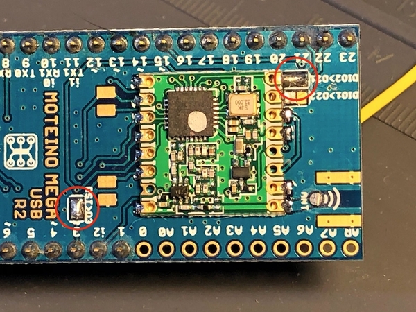
There are two jumpers on the back of the Mega that allow connections between the RFM69HCW and Moteino that are not enabled by default: one between D3 and the RFM69’s reset, and another between D21 and DIO2 on the RFM69. Both of these jumpers should be bridged with solder as shown below:
Connection to Legacy LCS
The PDI bus uses RS-232 at 115200 baud to transmit commands between the Legacy base and LCS modules. This presented a problem, because Mark’s original implementation used the Arduino SoftwareSerial library at 9600 baud to communicate with the RFM69. The SoftwareSerial library blocks while outputting to the serial port, and at 9600 baud it may block long enough to miss characters coming in from the PDI bus on the hardware port Serial1. (The RFM69 uses inverted signaling to transmit and receive data on DIO2, so we either have to use a software serial port that supports inverted signaling, or implement a hardware inverter).
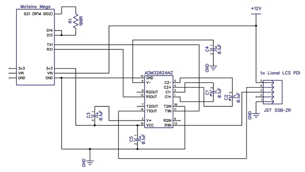
I used the AltSoftSerial library instead, which provides non-blocking write operations using the Arudino’s timer interrupts. However, AltSoftSerial doesn’t support inverted signaling, so I modified the library to provide an option for inverted signaling like SoftwareSerial. (“InvAltSoftSerial”). The library transmits and receives on pins 13 and 14, which are the output compare and input capture pins for the 1284’s 16-bit timer. Since the RFM69 transmits and receives serial data on the same pin (DIO2), I tied pins 13 and 14 together and connected them to DIO2 via Moteino D21 with a 100 ohm resistor (to limit current in case the RFM69 and 1284 ever try to drive the line in opposite directions).
Connecting to the Lionel LCS is simple: the RS-232 signal from the PDI bus is fed into an ADM3202 chip (which is equivalent to a MAX3232). The ADM3202 converts the RS-232 signals to TTL 3.3v signals that are read by the 1284’s second hardware serial port (Serial1).
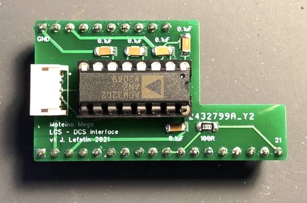
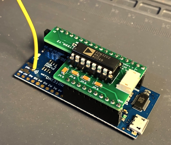
I created a simple PCB that can be plugged on top of the Moteino Mega with female headers. A JST header is provided to plug in the PDI cable from the Legacy LCS bus. This version uses 1206 surface-mount capacitors and resistors, but I designed a version that uses through-hole components as well:
Software
The Legacy Command Base will echo any TMCC or Legacy commands it receives from the CAB-2 onto the LCS PDI bus. The Moteino reads the packets coming in on the PDI bus, and parses any TMCC or Legacy 3-byte commands coming from the Command Base. (Legacy also has more “multi-word” commands used for more complex lighting and dialog effects, but the current version of the software doesn’t attempt to parse them.)
The demonstration sketch shows two simple uses of the CAB-2 to control a DCS engine: controlling the speed of an engine, and opening the front and rear couplers. Those are simple conversions of Legacy commands to their DCS equivalents.
Providing full control of DCS engines with the Legacy remote will require mapping many more Legacy commands to a corresponding DCS command sequence – and some of them, like sound commands, do not have a simple DCS equivalent. That project is not something I have the appetite to take on, so my hope that other people will be inspired to take the system further!
If you are interested, the attached ZIP file contains a schematic and Gerber files for the PCB, the demonstration sketch, and the InvAltSoftSerial and other libraries used by the sketch.


