You nailed it. Those values look "correct" for the circuit at hand and I've updated the schematic. This schematic ought to be useful for guys who take a crack at repairing or modifying the circuit board.
I'm assuming you would like the tower LEDs to work.
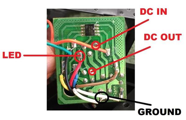
I'm thinking you can use some portion of the existing circuit board for both the LED and motor control. To that end, can you make the following 3 DC voltage measurements. Obviously the circuit needs to be powered. The black test lead on the meter connects to the "GROUND" point in all cases. I realize the motor lifts as soon as you apply power - but since you can only go up or stop, I figure you must have come up with a way to dis-engage the gearbox or transmission while the motor runs? The measurement for LED voltage should be made with the LEDs connected (I realize they are not lighting up).
If all's working you should probably get something like:
DC IN - between 15-20V
DC OUT - about 9V
LED - about 2V


