Apparently your meter displays "1" to indicate a measurement exceeds the range. That is, the leftmost digit on your display is a "1" so for the 20 range, the max value it can display is 19.99. For the 200 range, the max value is 199.9. BTW, I think it may be time to change the meter's battery.
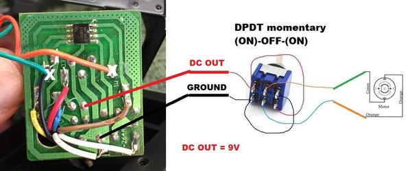
Anyway, given your measurements I concur with Leo that it's just the motor drive chip that has failed. Again, I don't think you can find the chip and given the apparently high failure rate based on other reports, I don't think you want to bother. But the board can be used as is to drive the tower LEDs. And you can use the regulated 9V DC voltage from the board to feed the DPDT bypass switch and drive the motor. So one approach might be:
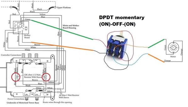
This requires NO additional components other than the DPDT switch. As drawn, once could simply cut the green and orange wires that go to the motor**. Then run these 4 wires (2 out, 2 back) to the DPDT switch. It's hard for me to appreciate the tight quarters since I obviously don't have the bridge in front of me. I figure running those 4 wires from the tower control box down to the base might be a problem? The wire gauge just needs to be similar to whatever the green and orange wires are - they look like maybe #22 or #24 gauge?
I suppose you could physically relocate the board in the base...then only 4 wires (2 to the motor, 2 to the tower LEDs) run from base to tower box. Again, this would require no additional components but there would be more soldering, splicing and re-routing of wires. Hard to say which way to go.
I suppose any method that runs additional wires between base and tower could use black insulation wiring to disguise them since the tower structure is apparently black. Maybe one of the guys that has actually made the DPDT modification can solve the wiring conundrum.
As for DPDT switches for this application, 99.9% (there's always some odd-ball!) have terminals in the 2 by 3 matrix configuration as shown. The corner terminals are connected in the criss-cross fashion - this effects the polarity reversal.
**Added note. This only "works" for FrankM's special case because apparently the board is stuck in the motor "on" condition even when the lever switch is in the center-off position (or even completely disconnected). For the more general case, one approach is to tap the 9V DC OUT voltage from the board - this does require some soldering of wires to the back of the board.


