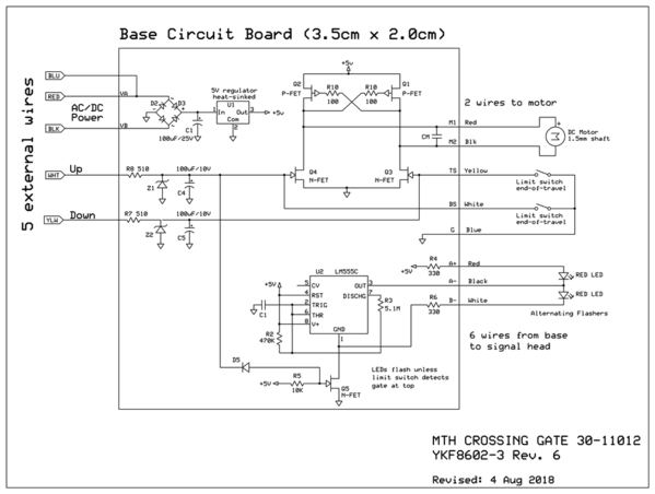
Take a look at this OGR thread where I posted the following:
When the gate is up, it mechanically closes a limit switch which turns off the flashing. There is a gate top adjustment screw that alters the angle of the up position. If the gate never hits the limit switch, the flashers will always be on (as long as power is applied to red/black).
The blue wire is the common to the relay's NO/NC outputs. If you are using an MTH ITAD or Lionel 153IR you don't need the blue wire since the ITAD or 153IR internally connects its relay common to power. As shown in schematic, for the unit I disassembled (Revision 6), the blue wire is the same as the red power wire.
You use the blue wire if you have a 153C-like contactor/pressure-plate to trigger the gates, or a SPDT toggle switch to manually control gate up/down, or an SPDT relay if using insulated-rail triggering.


