Chuck,
[PLEASE, LOOK INSTEAD AT THE TRACES I POSTED FEB 4 AT 1:34PM]
Your are correct, and it was my mistake when I wrote 6V p-p. You see, the 6V p-p is what I read when I used the signal diode instead of the 1N4004. The amplitudes I was getting did not make sense, so I tried it several times, but the results kept varying, so I gave up on that test. However, when I wrote that post, I looked at the 'last' setting I had on the scope, and it was 1V/Div, which was correct when I was using the signal diode, but not for the 1N4004. I re-posted (below) the traces with the scope connected without the diode.
Dale,
I know what the diode is for, but I thought I would see how the signal looked on the scope with the diode in series with the U-Term; that is, between the scope and the U-Term - just as if the scope were the multimeter. The signal was distorted, and it is not what I expected, so I used a signal diode instead. With the signal diode the signal was not distorted, but the amplitude was about twice as it was with the 1N4004. I have not posted those traces.
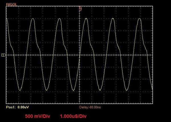
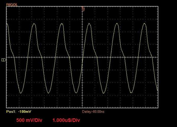
The signal is not distorted when the scope is connected directly to the U-Term and Pin-5 (with the resistor across Pin-5 and U-Term) whether the track is connected to the U-Term, as shown by these two traces.
Track NOT connected to the base.
Track connected to the base.
Sorry about the confusion.
Alex


