


Nice design and very nice boards!
As you pointed out in your posts, the decoder's AUX outputs act as low-side switches, so sometimes you might want to use "low-side" high-power switching of a device, controlled by the decoder AUX output. This application sometimes arises when you have common-power supplying multiple devices, and the decoder’s AUX open/ground outputs control each device separately.
In this case, you might employ a pair of N-channel MOSFETs in a package such as ZXMN3G32DN8TA (similar to the DMP3085LSD-13 package in your post) in the following straightforward circuit.
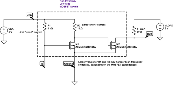
As the decoder's "IN" opens/grounds, this circuit will correspondingly open/ground on the "low-side" of the device.
An advantage of this design is that the device’s load voltage, VLOAD, can be different from the switch’s supply voltage VDD, which helps reduce power consumption of the switch by keeping VDD small. This feature is useful when controlling higher-resistance (in the 20-30 ohm range rather than in the 8 ohm range) smoke unit heaters that might require VLOAD=14V or so to work well. The down-side to this design is that you need to use both MOSFETs in the package to implement a single switch.
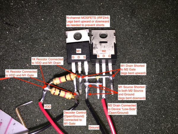
I have prototyped the circuit above with IRFZ44 N-channel MOSFETs, which are overkill, but are what I had on hand, and they work OK when using this switch as the high-power, low side control of an ESU smoke unit in testing with a LokProgrammer in conjunction with ESU 53900 Profi Decoder Tester mounted with a LokSound L V4.0.
(Parenthetically, the ESU 53900 Profi Decoder Tester could not source the power needed for an attached ESU 54678 Smoke Unit, even with a 14.8V LiPo battery supply instead of the puny AC to DC power adapter provided with the Profi board, so this problem precipitated testing this switch circuit!)
As you can see, the circuit is straightforward to “whip up” with about 5 minutes of soldering. Of course, for “production work,” I would cover the exposed electrical connections with Liquid Tape or the like.
Circuit simulation reveals that increasing R1 and R2 beyond 1K will hamper high-frequency (20kHz-40kHz) response due to the somewhat large IRFZ44 capacitances.
The "proof in the pudding" video.
Again, thanks THOR73 for your posts! Your design is invaluable.


