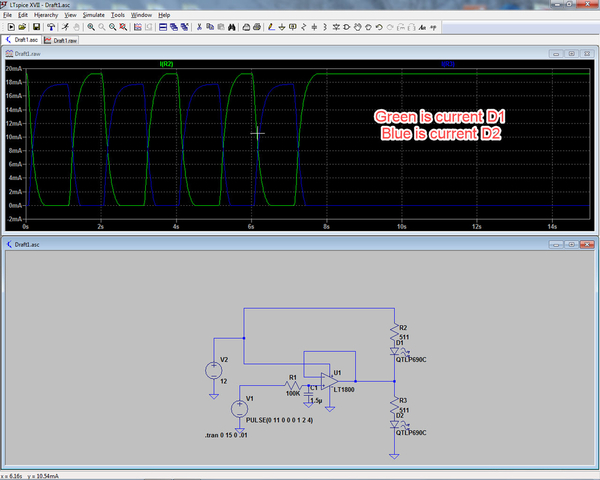
Caveat - I am not a very good analog designer, but here is a possible way to control current ramp through LEDs. Uses an Op Amp that works with a single supply, and can source or sink 20ma at its output. In the schematic, V2 is set as a 12VDC supply, and V1 is a one second on/one second off 0VDC to 11VDC pulse train to simulate your desired light blinking. So if this is a viable approach, maybe some much better analog designer than myself can make this a more workable design.
Second point, if you want a bit of a variable frequency, but also want to keep a 50/50 duty cycle, you can do that by using an edge triggered flip flop configured as a divide by two. Each rising edge will cause the flip flop to change state. Since only the rising edge of the clock input is used, the on/off time is not important of the clock is not important.


