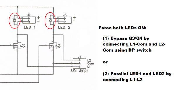
Right. The multivibrator is running and attempts to alternate Q3 and Q4 but the FETs are both already "on". No harm to the FETs in doing so.
Though I'm not clear on J4 being a 3-terminal "jumper". If this is really a connector with 3 wires going to the 4 terminals of a DP switch then OK.
BTW, if you have the breadboard still set up try simply connecting L1 to L2. This puts both LED1 and LED2 in parallel. When Q3 turns on, it drives both LEDs. When Q4 turns on, it drives both LEDs. So in effect both LEDs are always on! Then this only requires an SPST switch to force the solid on behavior. Q3 and Q4 now drive 2 Amps (instead of 1 Amp) since when turned on they individually must drive both 1 Amp LEDs. But The IRF540 can handle this. There might be a slight discontinuity in brightness when the transistors ping-pong due to component mismatch which is why I'm suggesting you give it a literal test-drive. ![]()
Separately, upon reflection, I figure these large LEDs might be mounted some distance from the board. Wires have inductance so it is good design practice to install a 5-cent diode at the FET outputs. 1N4003 is fine. This clamps any inductive spikes when the 1 Amp of current is suddenly switched off.


