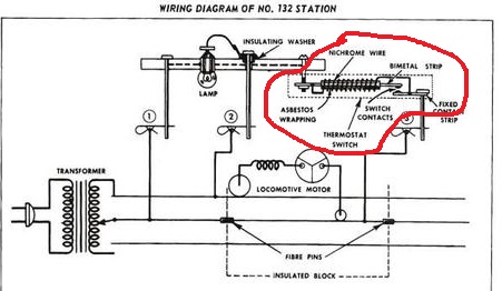
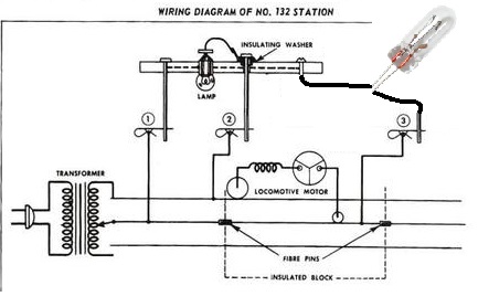
Here's another less-than-$5 alternative for the 132 thermostatic switch that DOES NOT use the insulated-rail trigger. In other words, you can use the existing 132 stop section which has "continuous" outer rail power on both outer rails. You don't have to mess with cutting the outer-rail or using track pieces that can be configured for insulated outer-rail joints. Also, the the insulated rail method can by problematic for trolleys (and SuperStreet vehicles) due to potential intermittent outer rail contact to the wheels of light-weight chassis - your mileage may vary!
This method replaces the $25 (and up) hard-to-find Nichrome thermostatic switch with a 10 cent O-gauge 14V (or so) lamp bulb that you might find in any conventional engine or the bulb in a lockon or turnout controller.
So when the trolley or engine enters the stop section, the lamp steals all the track voltage thereby starving the trolley/engine and it stops. In the thermostatic switch method, the Nichrome heater wire resistance stole the track voltage.
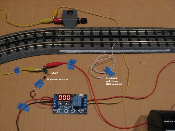
Now, the lamp turns on when the trolley/engine enters the stop section. In the thermostatic switch method the Nichrome wire started to heat up when the trolley/engine enters the stop section. The lamp illuminates a 10-cent phototransistor which applies the electrical trigger to the timer module when it sees the light from the bulb.
Otherwise, the operation/setup of the timer module is as before. That is, when the timer module is triggered (when trolley enters the stop section and turns on the lamp) it starts a 7-sec delay where track power is held back from the trolley - the lamp is ON and continues to starve the trolley of any track voltage. Then the timer turns its relay ON for 3-sec which applies track voltage to the stop section. The trolley starts up and exits the stop-section reaching the already powered section of track and continues on its way.
I realize there is a very limited audience for this but just wanted to document the concept before I dis-assemble my prototype. Note-to-self: this method allows use of an bridge-rectifier AC-to-DC voltage module to provide DC power from the AC Accessory voltage. This is because the lamp-phototransistor is itself an electrically-isolated interface (i.e., it's an opto-isolator) which allows a shared DC and AC common (typically not allowed when there's bridge rectifier in the mix).


