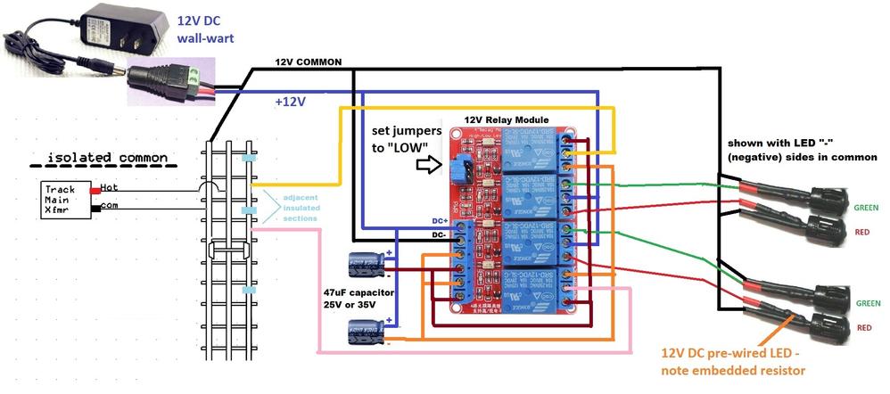
Consolidated Leo posted:Lets give this a try. The 12 volt common power connects to the outside rail so that the wheels will act as a switch to complete the circuit with the insulated rail sections. The 12 volt power feeds the relay board at DC plus and minus. The 12 volt plus also goes to the COM inputs of relays 2 and 3 which are switched to display either RED or GREEN LEDs. The GREEN connects to the normally closed (NC) outputs and the red to the normally open (NO) outputs. So the aspects will both show GREEN with no relays activated.
A northbound train hits the first insulated rail which connects 12v common (yellow) to the COM input of relay 4 (the one at the bottom). That routes through the NC output (orange) where the capacitor cleans up the signal and activates relays 1 and 3. That changes the southbound aspect to RED but leaves the other GREEN.
When the train hits the second insulated rail, the connection to COM at relay 1 (which is already activated) is routed through the NO connection to the orange trigger input. Relays 1 and 3 stay activated so the signals stay the same. When the first block is vacated, relay 1 continues to hold relay 3 at RED. And when the second block is vacated, the relays all turn off and the aspects return to both GREEN.
The same occurs in the opposite direction. Only the names have changed to protect the innocent. Nicely done, Stan!
Hi Stan, Just wanted to get your opinion on how far I might want to put the isolated sections from the signal bridge? Just waiting on the capacitors, got the 8 block relay module 2 days ago.


