@GeoPeg posted:
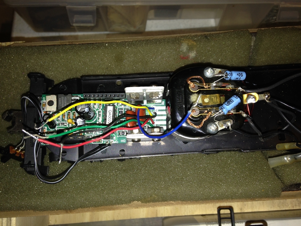
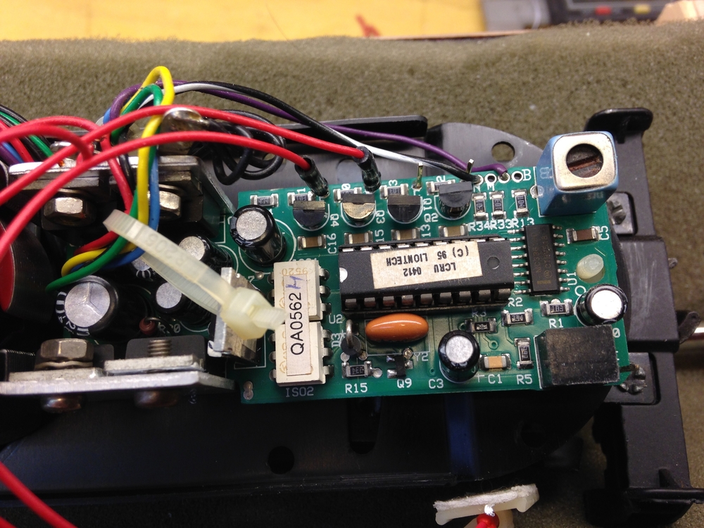
One of the two 10-pin sockets has two jumpers in place – purpose? Some of the pins on the opposite socket have pcb traces running to them, but no jumpers are present, so they may serve some function? I was really hoping to get some directional lighting off this board, but don’t know if that was part of the design.


The purpose of the socket was to accept a daughtercard that was the earliest of early versions of TMCC. I personally have not seen the documentation or part numbers of such a daughtercard, but again, with some level of certainty, this is where the LCRU and later LCRU2 started from.
To my knowledge, no, there are not outputs in those pin headers- not in the sense that you are asking. Instead, those are INPUTS- specifically the directional control from again, a plug in TMCC radio receiver board from the earliest of "Liontech" days. EDIT- the "jumpers are connecting the F-N-R logic built into this board (chip under the regulator) to the motor drive section. When you plugged in the special digital upgrade tmcc receiver, likely it got AC track power, common, this regulated 5V for digital logic, and provided the pulsed forward or reverse motor drive signal in place of the jumpered F-N-R reverse logic.
maybe @Norm Charbonneau knows something? https://ogrforum.ogaugerr.com/...8#157406524839422998
Early LCRU from this topic https://ogrforum.ogaugerr.com/...-lionel-gg1-question
My own post from the past
@Vernon Barry posted:Or maybe you mean the really early version???? https://ogrforum.ogaugerr.com/topic/lcru-e-unit-help
I personally have never seen the plug in daughtercard to make this TMCC.