


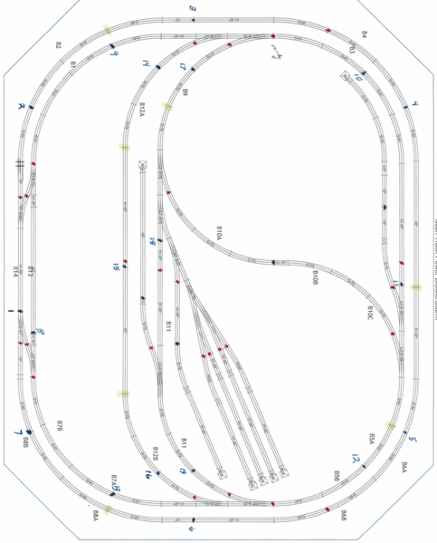
Bryant Dunivan 111417 posted:The photo attached shows the power connections (blue) from each terminal of an MTH Terminal Block. It also shows the center rail insulators (red). My thought was that the voltage would travel all the way from power connection (point 13) up through the 2 switches. I don't have voltage all the way through the top switch. Voltage and continuity end at the snake looking piece to the center insulator on the entering side of the switch coming down. I would have thought the center would be jumped all the way through on the straight. Also, I cant figure out why I need to insulate the common outside rails going into the bottom half circle between power points 14 & 16. They are fed by MTH terminal block #2. The power for the track outside of that is coming from MTH Terminal block #1 Each MTH terminal block is separately fed by the 2 variable outputs of the Z-4000. I thought common mean't just that? Any insifght or help would be appreciated.
I don't have voltage all the way through the top switch. Voltage and continuity end at the snake looking piece to the center insulator on the entering side of the switch coming down. I would have thought the center would be jumped all the way through on the straight.
The switch closest to 13 is stopping the power. Check continuity (power off) across track joints moving from 13 to the snake pair. On the switch, across the two center rails and then, thru center to turnout center. I mentioned before, the switches expect power from the adjoining track on all three ends.
Also, I cant figure out why I need to insulate the common outside rails going into the bottom half circle between power points 14 & 16.
it sounds like a clumsy way to create a passing siding to kill power to park a train. It may be to keep the center tail receiving DCS signal, when you get there.
You need one terminal of an On/Off switch to go to common on the MTH terminal board. Then, you need to connect the common wires from that space to the other side of the On/Off switch. That will permit parking a train there and turning off power.
You are doing well for your first layout wiring. Be patient, this is how to learn. The advice you receiving is shortening the learning time for this not so basic wiring.
You are close. A couple of jumpers on the snake switch center rails and you will be close.
Will you want to kill power to any of the yard spurs? Do the same as the passing siding. Switch the common On/Off.
Get the layout track wiring up and running properly with the switches working. Take a break, and then go for the signals.
The layout does a lot and has good "play value". Plenty of space for scenery, buildings and such.
