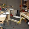
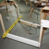
Clem, there's a bit of springyness to the door. You have to put a little pressure on the closing before activating the latch. It doesn't seem to need any downward force, so I'm going to use it as it is before making some additional modifications.
Now onto today's activities... I made a minor adjustment to another OSB panel that wasn't on the same level as an adjacent panel. I tried the belt sander routine to reduce the height of the higher panel, but there was too much stock to remove so I went to my tried and true, Plan B which was to shim the thinner panel's splice plates under the panel to raise the low piece enough to make it flush. I had to put in about 1/16" of cardboard and it worked. It was flush and I didn't need to generate any more sawdust.
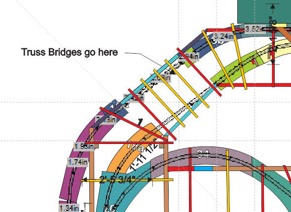
With that, work formally began on the bridge end. Here's two views of what I'm attempting to do here. First is the plan view of the final structure design, based on what I actually installed today. The light blue L-girders are 23" below the main girder level and are 31.5" long. For the inner one, this spanned the entire distance between the adjacent girders, whereas on the outer one, I had to build some connecting girders that tied into the existing structure at approximately a 45º angle. The original OSB pieces for this corner no longer conform to the new design so I'm going to cut some new ones out of the scrap I have left. It's the light green pieces in the plan drawing.
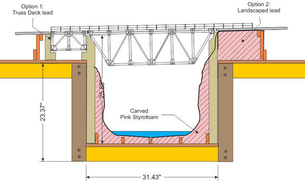
And this is the elevation of what the deck truss bridge will look like. There are two options shown. No. 1 is using additional box trusses are lead-ins to the main span, and No. 2 is using earth works leading to an abutment. All of the earth work will be carved pink Styrofoam. I have a hot-carving unit that eliminates all of the plastic from flying around. The bridge is accurately scaled from the kit that I bought.
And here's the structure itself. For the inner structure I had to drop 1 X 3s directly from the existing girders and then using Simpson splice plates, join it all together. For the outer, I made some small 16" L-girders to extend to the existing structure, and then used 2 X 2s for the drops. Across the bottom is the other L-girder. In this case I went with the carriage bolt fastening scheme. Tying the L-girders together will be a grouping of 1 X 3 and 1 X 2 joists. The bridge abutments and scenery will be supported with these joists and it will tie everything together as a network.
Looking from the inside to the outside
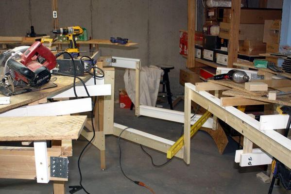
Looking outside in
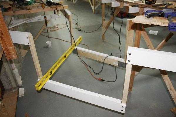
As I was screwing the screws into the Simpson plates, the lumber started splitting so I had to resort drilling pilot holes for all the rest of the screws. This solved the problem.


