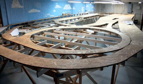
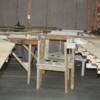
Well... the benchwork is officially done. I completed building the temporary bridge for the middle-bridge section. When I'm ready to add the real bridges, I just have to remove the three temporary fillers and then build the abutments, etc. and install the new ones.
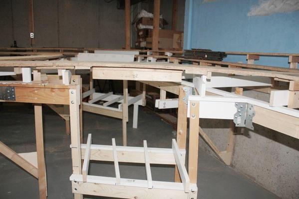
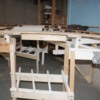
You can see the stiffening rib under the temporary filler. This thing is rigid enough for me to stand on.
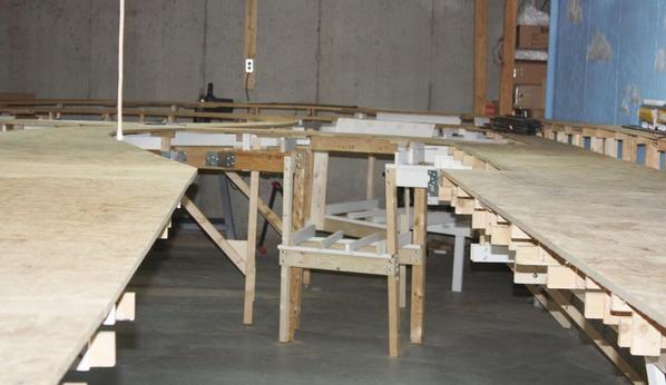
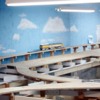
Here's a shot taken from the top of a step ladder showing all the benchwork. I cleared off all the tools, trash, etc. in preparation for this shot.
And here's my MTH Veranda which couldn't wait to try out the high line. Big layouts make O'gauge, scale-length engines look good.
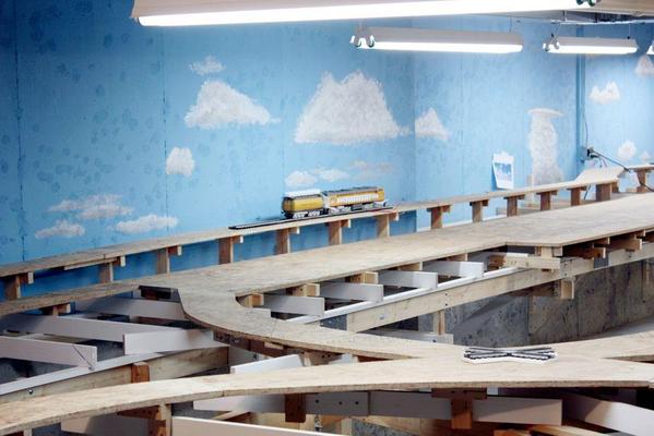
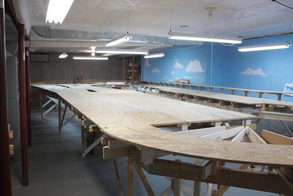
Here's a reverse angle view. Looks like an empty 'artist's canvas' just waiting for something creative to happen...
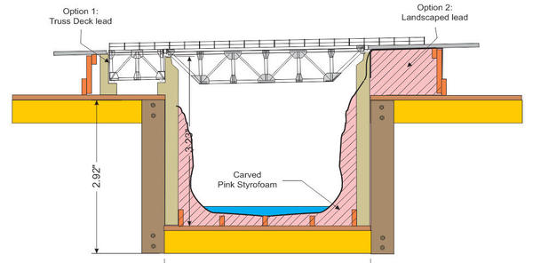
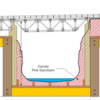
I've been doing research on how the Plastruct Truss Bridges should be configured now that I'm turning them upside down and converting them from a through truss to a deck truss. The bridge doesn't have to be as high or as wide since a train with over-height freight cars doesn't have to pass inside. So I took the scale drawing of the original design and narrowed it and reduced the height. In the Kalmbach "Bridges and Trestles" book I found some drawings of single tracked deck bridges and it looks like the trusses are centered about where the loading gauge of the engine is, and was stated at 9'-6", roughly double the track gauge.
Here, I hung the new plan under the temporary span to see how it looks and fits. It works well and the proportions seem right. Since all the components of the bridge kit are "cut your own", I should end up with extra material which be used to build the plate deck bridges that are going to span the middle bridge gap.
Here's the newly proportioned bridge on the previous plan. The height of the truss looks about right. The previous version was too deep for the length of the span. The shorter the truss members, the greater their compression carrying capacity, however the longer the tension members are the greater tension they can carry.
I found some screw points sticking through some OSB on the far end that I had missed. I'll grind them off next session. Then, I'll vacuum the entire surface (and the floor) in preparation for track laying. I'm actually going to be building a model railroad not just the world's most complicated work bench.


