Work was very short today since my client has just moved to a new location and didn't need a consultant hanging around. I just checked in to see if things were going as planned and left. That gave me some serious time to continue working on the control panel.
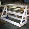
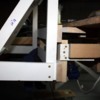
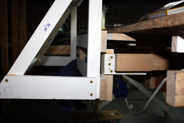
Here's the panel frame clamped onto the braces that are in turn assembled to the joists under the layout.
The top rail will be held with SPAX screws, but the lower section will be held to the braces with carriage bolts. All the braces are screwed AND glued with Titebond.
Here's the suspension structure. It's 1 X 3s with a 2 X 2 hanger. There will be two points of suspension.
The back, bottom and sides will be sheathed with 1/4" ply to which all the circuitry will be fastened.
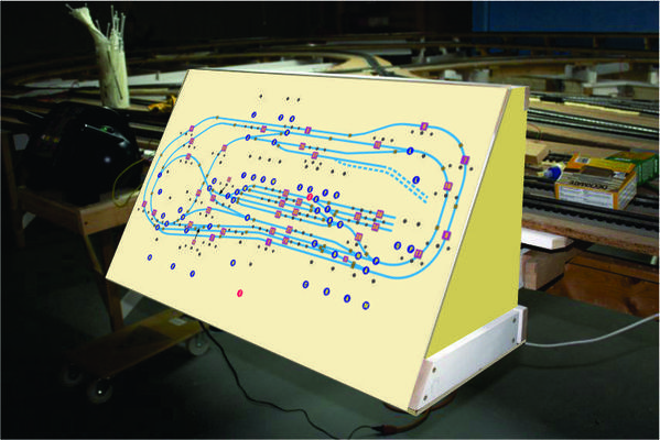
Here's an artist rendering of the ply installed
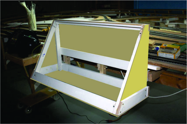
and another artist impression of the final job with the panel in place. Aren't graphics programs cool?
I hope someone can help me understand how to power all the indicator lights with LEDs. I understand they're DC and that polarity is important and that you must limit the current to each one. But is there a way to feed all of them so that you don't need the resistor at each LED. I've got 74 of them on this panel. There's a green and red at each block and there are 37 blocks. I think I'll pose this question on the electrical forum too.


