Started to officially wire the layout today. Did a little this morning while grandson #2 was building a space alien with modeling clay, then got involved in building the Motorized Marble Madness Machine by K'nex. It's a monster project which gets built and torn down every couple of years. The kids love it. But, I did get back down to the shop this evening and got a little more done.
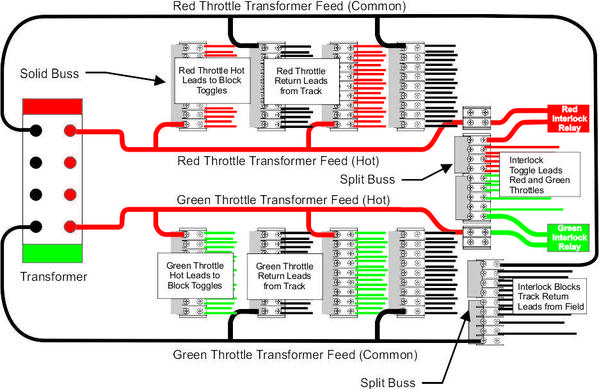
I fastened all the barrier strips to the cabinet floor based on this schematic I drew yesterday.
Barrier strips alternate being 'hot' and 'common' with the throttles (green and red) down each side. I have enough hot terminals for one wire at each since some will come off the interlock strip on the right side, but some of the commons returning from the field will be doubled up.
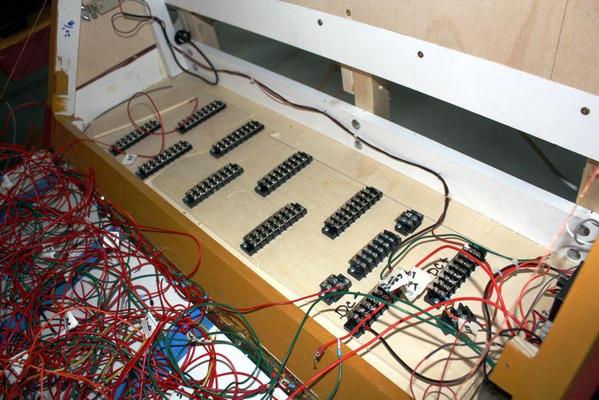
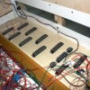
Here's the barrier strips screwed down to the base. I doubled the ply in the base since I was using a 3/4" screw and it would have poked through the bottom. Doubling made this problem go away.
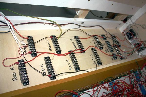
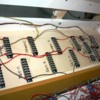
The barrier strips all have jumper bars so they each have 16 screw terminals all with the same voltage. The center strip in the right end with the 6 terminals has a split jumper forming two 3-terminal strips. This is where the interlock blocks will get power. It's interrupted by the relay circuit. The interlock leads are fastened in this view.
Here's the power wiring in place. I went around the layout and replaced some of the "American Style" barrier strips with "Euro-style" ones, and of course I ended up reversing the polarity.
When or if I go with MTH's DCS digital control, I will substitute the power feeds from the red throttle with the feeds from the DCS. The rest of the wiring will remain exactly as it is since I'm already using "home run" wiring with heavier gauge twisted-pair as they recommend. If I didn't intend on ever using DCS, I wouldn't have been as particular with the barrier strips and would have used a ground loop for the common returns instead of bringing every common back to the control panel. But this gives me flexibility and I can add the control system whenever I want.
I turned on the transformer to make sure that all was okay. The idea here is to install one circuit, test and verify it and then move onto the next one. So I turned it on, the engine on the track made some funny sounds and didn't move, the other channel on the transformer was showing voltage and current loads, and then the overload light lit. I pulled on the leads from the "Red" channel which was NOT going to the track and the short still existed. So I realized it must be something out of the panel. I checked each of the places where I exchanged the strips and there it was.
I put the blue wire into the hole with the brown wire on the other side and vice versa. Dead short! Exchanged the wire locations and there were no more shorts. I'm not colored blind, but screwups like this make me wonder...
I have more meetings tomorrow, but I may get some more time in the shop. I have to buy larger lead ends for the 14 gauge wire I bought for the long runs. The ferrules and spade lugs I have are not large enough.


