Back to train layouts...
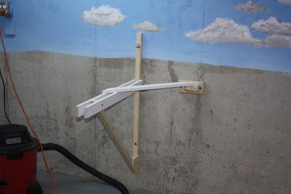
Installed the last wall bracket today so all the concrete drilling is now complete...gladly.
I did some checking. The pull out and sheer strength of the 1/2" wedge bolts is both 4,600 pounds. The weight of the entire railroad won't be anything like that, so I have no worries at all that the brackets can't do their job effectively. The wood itself will shatter before the bolts leave that wall.
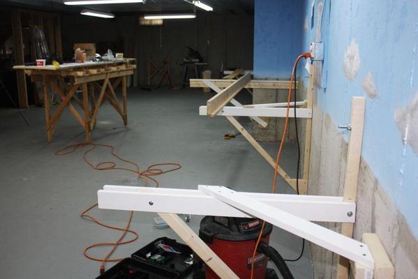
Here's all five wall brackets now in position.
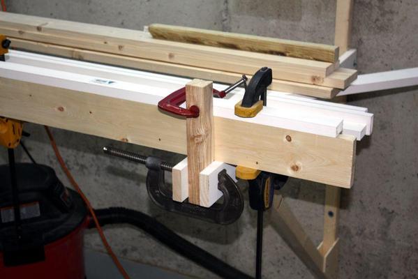
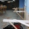
With the brackets in position, I was ready to start making L-girders. I don't have a work table available for an 8 foot girder-making job, so I put the brackets into good use already.
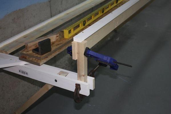
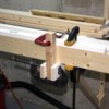
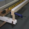
I'm supporting the 1X4 on its edge by inserting a 2X2 between the horizontal bracket rails held with a c-clamp, and then clamped the girder web to this.
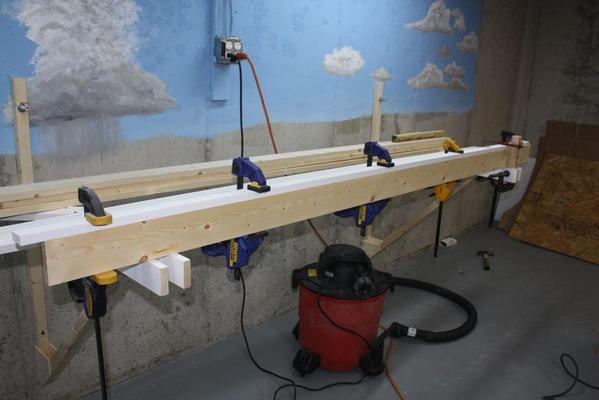
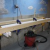
With the web stabilized, I was able to clamp the 1 X 2 flange on top in prep for screws and glue. This process goes pretty fast and I was able to glue up four girders that will stretch the entire length along the wall across all brackets in a little over an hour.
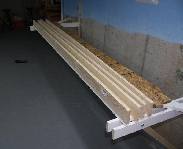
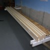
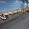
Here are four girders waiting for the glue to dry. I offset the flange by 3 cm so the flange and web don't fall directly in line with each other. The longest run which goes across the back wall from one end to the other will use 3.9 girders spliced together so these four represent 1 long girder.
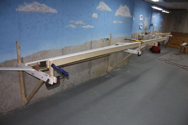
While they were drying, and before I remove the screws, I decided to start figuring out how to mount them onto the brackets. As noted earlier, the first brackets I installed are about five inches lower than they should be, so I need to put a riser in place to end up with a level girder. Here's the riser in place that levels the girder with the corner bracket (which is at the correct height).
Notice how neatly the 2 X 2 sandwiches between the bracket horizontals. I'm going to use one or two carriage bolts to fasten the riser to the brackets and the girders to the risers.
Here's another riser at the other end. Each riser is 10.5 inches long and the flange rests on the top when level so putting it together will be a snap.
Nothing's in its proper place here, but the theory is now proven. Next session, I'll remove the clamping screws from the flanges and start mounting the girders AND splicing them together. In Kalmbach's Benchwork book, they talk about using a piece of web that 2X its width in length to bridge between to girders to make a splice. When I built the layout in Germany, this is how I did it, but when I enlarged it in Pennsy, I used Simpson Strong-tie metal hardware to make the splice. It worked well and was easier to work. Splice plates are used on both sides of the web with lots of fasteners.


