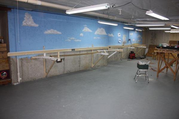
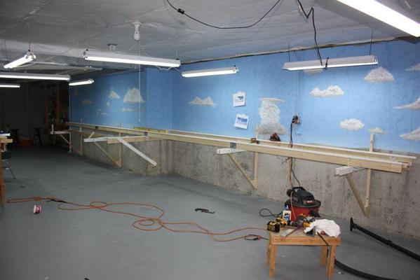
It's amazing what you can accomplish when you have three solid hours to work on the project. I got the two rear-most L-girders in place, leveled and tied in. This required building two more 8' lengths and installing them. I used two different means of tying the girders to the support structure: deck screws or their equivalent, and 1/4" carriage bolts. For the rail that butt up against the bracket vertical support I used the deck screws since there was no effective way to get behind the bracket for the other side of the bolt. But on the free-standing connections I used carriage bolts which are immensely strong and really lock the structure together. The long 32 foot girder is not dead straight when sighting down its length, but it doesn't have to be. The joists that go on top, just lie across the girders and are fixed at each end with one screw. The amount their ends stick out doesn't matter.
Here's today's progress looking from both directions.
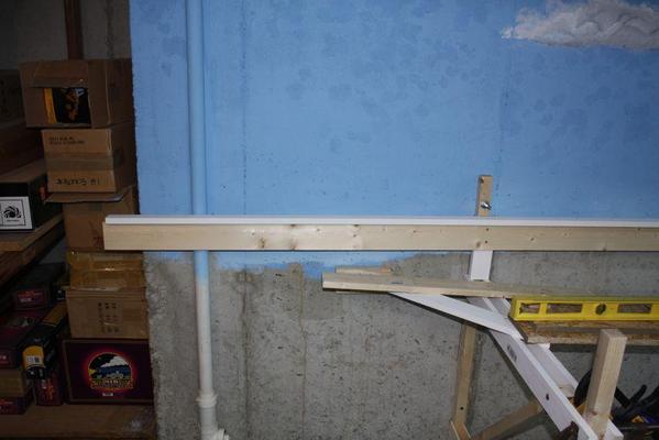
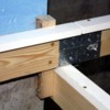
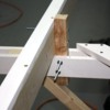
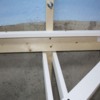
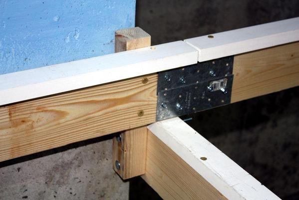
Here's some details of the joinery involved.
In the first instance, I used carriage bolts to hold the riser to the beam since I could see both sides.
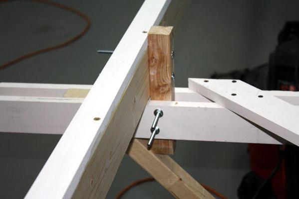
This next one is a full, free-standing support. You can't help noticing that the carriage bolts are wayyyyy long. I'll trim them with the Dremel and a cut-off disc in the next work session. I was getting tired and didn't want to tackle a step that could easily get a little out of hand. I didn't want to rush it.
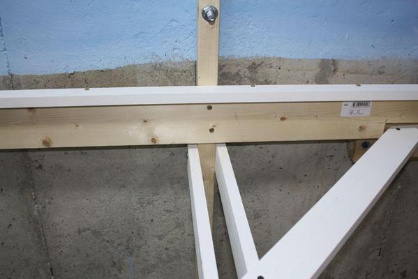
The last example is using deck screws into the bracket upright. You can see that it's sitting above the bracket due to leveling requirements. Note also, the relief cut I made so it would clear the sway brace. When I chose to install the sway braces on top of the brackets, I realized immediately that I needed to add relief. I used the saber saw to make the cut. The other choice was to mount them on the bottom of the bracket, but I didn't relish the thought of putting in the screws upside down.
While the straightness of these long girders isn't critical, it is important to make sure that they are square. I trued up the free-standing with a machinist angle block. Even perfect level isn't critical at this stage because the T-blocks and their risers are individually leveled and cross-leveled before the sub-roadbed is laid on top. I just like stuff level as I go along since it ultimately makes everything a little easier.
I used Simpson Strong-tie splice plates to hold the girders together. The plates are on both sides with 8, hex-head, self-drilling sheet metal screws holding them in place. They hold the girders very securely. I've used up my stash from the previous layout and I'll have to buy more. I have Phillips head screws that are designed to fit the holes in these plates, but they're too long and leave sharp points sticking out whenever I use them.
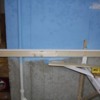
This waste pipe caused a slight field alteration. I had to space the girder off the bracket upright a bit so it cleared the pipe. On piece of 1X2 between the girder and bracket was sufficient. I just drove the screws through both pieces. I always drill clearance holes through the piece to be fastened so they pull down nice and tight. The layout turns 45º from the end of the back girders. There is a crudely constructed shelf just out of view on the left in this picture. It's holding all of the trains in their boxes right now. Once the layout is finished, I'm going to demolish it. I will give me more train space, or more access around that curve. The train boxes can be stored under the platform.
You can also see that the girder is lifted about five inches above the bracket. In an earlier post I explained that for some reason I built the brackets too low. I looked at my drawing and realized that when I first sketched it out in CorelDraw I wasn't actually worried about the height, I was just playing around with the structure's design. Somehow, I had forgotten that this was just a notional sketch and I took measurements off of it. Of course they were wrong since I never used any when making the design. In the other two brackets, I compensated by raising them higher up the wall so I didn't need to lift the girders.


