Worked on trains today too.
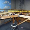
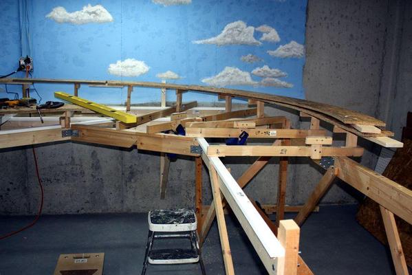
Right end is shaping up. Using the RR Track drawing that spells out the track elevations. It gives the elevation at the center of each piece of sectional track. My risers don't necessarily match up 1 for 1 to those track pieces so I had to interpolate the elevations which fell at other locations. Again, like the straight run, I set up a lower riser, an intermediate one and then used the string line to establish the position of all the rest.
Before I did this, I had to finish up the foundation work. I tied the right end girders at two points with right angles using attachment blocks and carriage bolts like I did with the angular girder way down at the other end. I had to extend one of the rear girders so it reached he right end's girder. I also attached a diagonal girder across the angle which gives me a strong point to attach as set of radial joists which support the curves.
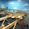
Here's a shot that shows the radial joists. When I build this layout before, I didn't do it this way. I just ran joists diagonally across the corners and mounted the risers edge-wise to them. This was not very secure, but it avoided making more girders. This new method allows risers to be mounted conventionally to each.
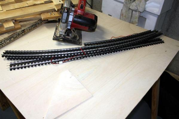
To be sure about how far out the elevated curve OSB had to hang out over the end structure, I broke out some actual railroad track. This was a major event since it was the first time this track saw the light of day in 3.5 years. I put together the corner curve and the little bit of straight section that runs across the back and—with the curve OSB temporarily clamped into position—aligned the track with the center of the OSB and moved the OSB outwards until the curve looked right. Here's the track.
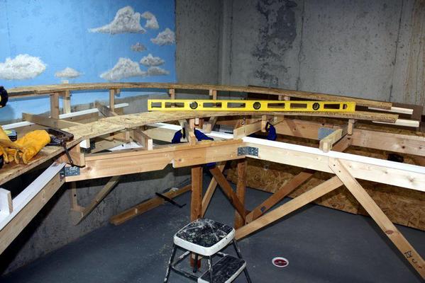
After positioning the OSB curve I started to fasten the risers to the piece. In a couple of instances, I had mounted the risers too far in, so I removed them, repositioned them and re-fastened them.
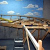
With the top piece down tight, I started to attach the inner, base-elevated OSB curve. This piece was easier to position since all I had to do was make sure it was level with the existing parts of the layout. I mounted the end splice blocks onto these pieces before putting them on the layout since it's easier to screw them when face down, instead of underneath the layout facing up. I still have to do that for the mating piece, but that's only one instead of two. In this picture, it's just sitting there. I will be fastened in tomorrow.
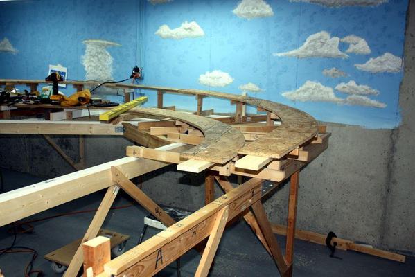
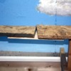
I have one correction to make. As I mentioned a while ago, I had changed the way I was drawing the tangent line to draw the ends of the curved pieces. I thought I was doing it better, trying to draw a line from the imaginary center of the arc inscribing the curve, but I was wrong. I will make a small filler piece to fill this gap. I will have to do this a few more times since the curves at the other end also have the same errors. Not a big deal, just a bit of a pain.
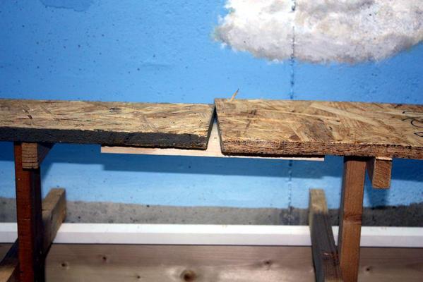
As you readers know by now, I don't just show you the good stuff, I show you all the stuff. The good, the bad, and the really ugly.
I now know the reason to maybe NOT use OSB for model RR construction. It's an "instant splinter driver". If I just look at it the wrong way, I get a splinter somewhere. Whenever I handle it, I wear serious leather work gloves, but as soon as I take them off to pick up a screw or something. BAM! I get another (&#%_)%T splinter. It's no wonder... the entire board is made of nothing but splinters! It is very strong! It's also very rigid and will ultimately make a great layout once it's all covered with scenery so no one can ever touch it again.


