Thanks Chuck and Clem. Before I get into today's session, I'll answer your question. It was strictly a budgetary decision. I simply didn't want to spend the $$ to do construction in the basement. I couldn't have stopped just at that wall and would have done much of the rest and this would have been more than 10 grand. It would have delayed building the trains again by a year at least. The basement's dry and not too cold. It's actually colder in summer than winter since the air leaking from the ducts push some air-conditioned air into the basement. In the winter it's heated air which tempers the room nicely. If I wasn't down there all the time, I'd want to plug those leaks since it's not very efficient.
I'll look for those clasps, Clem. I'm probably over-thinking this.
As to the build thread. I built an RC, B-17 (78" span, 1:16 scale) for a local RC pilot. I blogged the build on RC Scalebuilders.com. Apparently, great builders all over the world write detailed threads on the entire construction of these scale models. Some thread take years since some of the models are museum-level construction. I liked this and blogged my build. Then I did the same thing for my USS Missouri build on WorldAffairsBoard.com. So it just seemed natural to do the same on OGRR's site. It helps me think through the project to document each session's progress, plus lets others learn from my techniques and mistakes.
Now to today's progress of which was substantial.
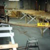
I finished putting all the joists on the front module. This included making some longer ones to span the widest part of the layout. At first I tried to make since pieces, but an 8-foot piece of 1X3 was not long enough to overhang properly on both ends. So I split the joists and had them overlap in the middle. I'm on the scooter the entire time doing this. I clamp and end, square it up, drill the pilot hole in the L-girder flange, put the screw in, then scoot across to the other end, clamp, drill and screw. The whole thing takes a little over a minute.
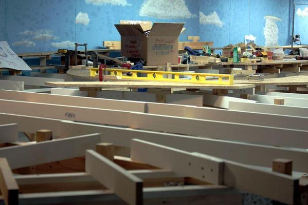
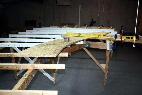
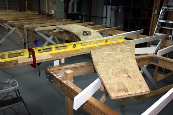
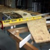
I clamped some scrap onto both ends of the bridge piece that carries rail across the middle of the layout to the "spider panel". I threw the spider panel onto the joists and aligning its mating end with the bridge piece. When positioned, I clamped a temporary risers to elevate the spider panel to a height of 43.25" off the floor which is the height of the OSB on the opposite side of the gulf. Finally, I clamped the bridge panel to the spider to stabilize it a bit.
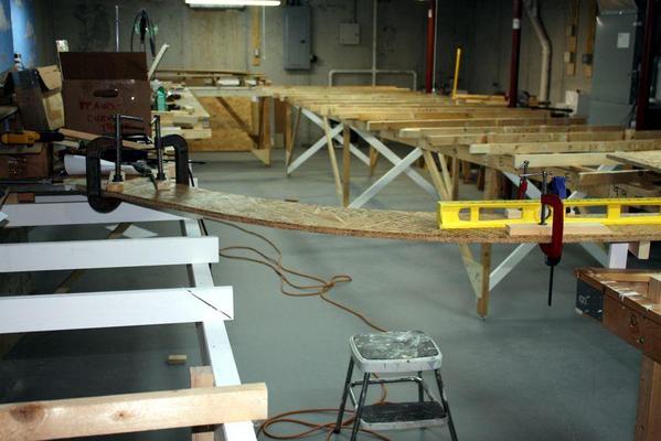
With the position correct, I started clamping real risers to various joists that lie under this panel, each time bringing it up to 43-1/4". Usually a hit or two from my rubber-headed hammer nudges them to the correct height.
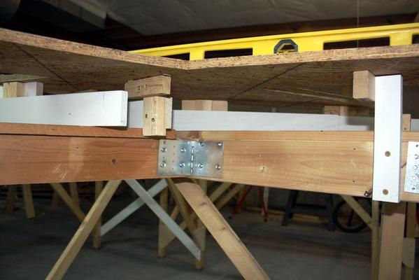
Once all the risers were clamped, the panel leveled and the height correct, I put one screw into each riser holding it to the joist and letting me take off the clamps. I removed the bridge piece and the spider panel setting it aside. With the risers now exposed, I use the head of a combination square which has a little level to level each head independently and then put in the second screw that holds everything in that position.
Before I removed the spider I marked the location of some strategic risers underneath so I could replace it in the same spot with having the re-clamp the bridge piece. I put the spider back on aligned on these marks and clamped it in a couple of places. I drove the 2" screws to hold the riser cleat to the OSB. Once all the screws were in it was solid and level. This piece will set the relationship of all the pieces on the front module as the layout construction expands out in both directions.
I'm not going to describe this process any more since it becomes repetitive. I detailed this one since this piece needed to be positioned in relationship to the bridge with set up the relationship between the front and the back modules.
Here's another process schematic shot showing how I'm doing.


