I've been working on the railroad almost the entire week and have made significant progress on the benchwork. I've have six pieces of conventional benchwork left to install with the rest being the swing-out portion and the area for the bridges. I've got a lot of pictures today.
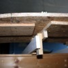
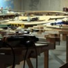
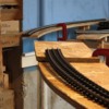
After I measured and laid down the left end elevated curve (actually its a grade that returns to base level) I was getting suspicious that all was not right. So I clamped up some pieces to better visualize what was happening and here's what I saw.
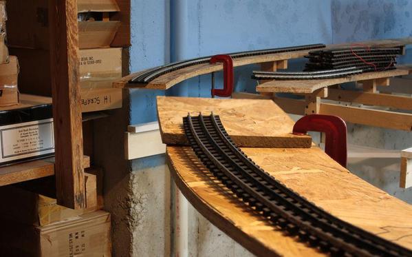
You can clearly see that both ends leading up to the gorge do not meet. I'm not sure why since I measured from the center of the inside circle to the center of the outside and used this dimension to position the outer curve relative to the rest of the installed road bed. So I removed all the screws holding the OSB to the risers and pulled the whole curve assembly out about five inches. I basically just sighted over the corner and stopped pulling when they lined up. It took less than a half hour to make the adjustment.
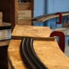
Here's the after picture. While it's still not perfect, I can work with it.
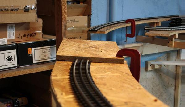
With that fixed, I glued filler pieces into the v-shaped gaps that showed up as I "bent" the curved piece to conform to the new pattern needed for the bridges; which BTW have been ordered and are in transit. They're kits by Plastruct and look pretty real. I may have to shorten their 30 inch length since I still don't have enough straight track leading into the bridges. My long steam engines have some significant overhang on the outside of corners and they may hit the bridge. Being kits of a bunch of structural steel replicas, I may invert the bridges and make a truss deck bridge. With all the structure under the tracks, the engines won't have anything to hit. I will have to make the gorge deep enough to give realistic clearance under the bridge.
Working around the curve, I tackled the big piece that I laid out backwards. It required a "radical" fix, squaring up the angular end that was backwards, and pulling in a filler piece that matched up to both pieces.
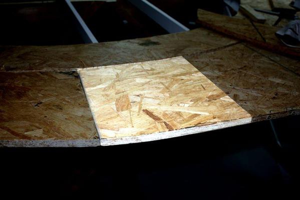
And here's the splice plates underneath that stiffen up the whole assembly.
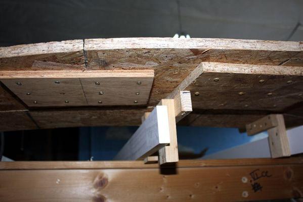
I'm using ply and OSB for splice plates instead of the Simpson Strong-tie plates, partly because I have too many screws sticking through that I need to grind off when I use the thin sheet metal plates. They're also stiffer. I'm making sure that I put the splice plates on each piece before it's onto the risers. It's easier to put them on at least one side when I can flip the OSB upside down and work standing up. Once the piece is one, I still have to put the screws into the other half working over my head, but it's only one side.
I then moved on from sheet to sheet. I'm now having to handle some pieces that are almost a half sheet of OSB and they're heavy; too heavy to push up in the air with a riser in my left hand and a quick clamp in my right. I needed a tool to help me out. This morning I realized I could make a simple jig that would support the sheet at the proper height making it easier to fit the remaining risers underneath. Remember; one end is already resting on the splice plates of the previously installed OSB panel, so I just have to raise the other end under it's level. The sheets are bowed in both directions, so I put the level between the high spots and push a riser into the middle until there's no gap under the middle of the level. Here's the jig.

I just lift the sheet, slide the jig under it and supported across a joist. It works. It greatly sped up the installation of the big pieces with less wear and tear on me. I don't place all the risers under the sheet. I Just install one at each joist with one screw. I then take the OSB off, level the riser cleat and put the 2nd screw in to fix it. Then I clamp the level to the top of the installed risers and clamp the other riser on the joist so it's pressing up against the level. I fasten this one with one screw also, level that cleat and then put in the second screw. This insures that all the risers are dead flat and at base reference. When I put the OSB back on top and start screwing the cleats to the OSB from underneath, it usually pulls out all of the warp and the sheet is dead flat. Neat!
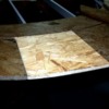
Here's what it looks like when the OSB is pulled off and all the risers are in place.
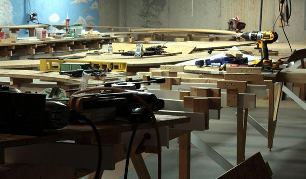
Here's the progress shot showing the sheet that was just being installed in the above picture.

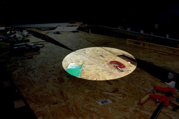
The next piece went in cleanly. The piece after that needed a little trimming to align perfectly to its neighbor. Here's a shot showing the edge that I needed to trim with the saber saw. It's getting easier to saw stuff since I have a lot of study tables all over the place to clamp a work piece to use the saber or circular saw. Speaking of saws, I think something's going wrong with my Craftsman Power Miter saw. After cutting a lot of pieces in succession, the auto-brake is not working or working intermittently. It just started doing this. It's not to scary since the saw has an effective blade guard, but I have to be careful when bringing the saw down to align another cut.
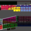
I've photoshopped this picture to highlight the area.
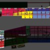
And here's the schematic showing where we are now.
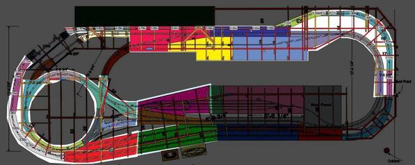
The gray OSB panels are added since the original design. When I added the run-through rail yard, I needed to put some wood into the gap. I'm also adding some rectangular OSB to fill in what would be just open joists. There are buildings and structures that are going into these spaces. All of the OSB will be done by the end of the month. We're taking a trip back East and my wife and I going to York. I used to attend them religiously even when I was living in Germany, I got the York show. Since we moved to Louisville, it became a bigger deal to get there. This will be my first visit in 3 years. Unfortunately, I've dropped so much cash on the rebuild so far that I may not be able to buy anything.
One thing that's sure when you almost double the square footage of a layout... it takes tons of risers and cleats. I've completely consumed all the risers from the earlier versions and now in production making new ones. Here's what that looks like.
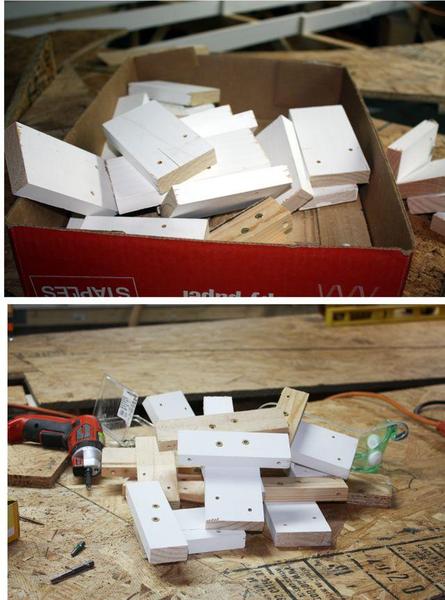
I thought I had enough 1X3 stock to make the riser leg. I had four 8 foot lengths of furring strips that I've had for years. However it is warped on it's length, and very dried out. When I screwed the cleat into it, it split in half. I chucked the whole lot of it and am using the fancy, primed finger-jointed stock, which I am now out of. I'll need some for the bracing on the bridge end and the swing-out so I'll probably get another 6 pieces. Having a drill press is an essential tool in this project.
The target is still to get trains running by Thanksgiving when my son and his family come to visit. My oldest granddaughter, Anna, is tech savvy and the trains.


