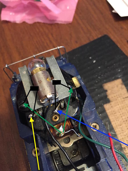
I'm on to the actual installation of the ERR AC Commander board. But I'm a little confused on the caps for the motor.
The yellow and blue arrows represent the power from the AC Commander board to the brushes. I've drawn in black cap representations. The AC Commander came with new lugs that I think I can place on the side screws of the motor (green arrows point to these) and then wire to common (which both of the green arrows originate from. And if I understand the instructions on the left side of the photo one end of the cap would go to this new common lug I've added on that side and the other end of the cap would go to the yellow brush power lug. And on the right side of the photo one end of the cap would go to the new common lug I've added on that side and the other end of the cap would go to the blue brush power lug. I'd take the common on the motor (where the two green arrows originate) to frame common. Does that look correct?
One other question - does it matter which leg of the cap goes to common and which leg goes to power? One leg is shorter than the other on the cap so that leads me to believe it matters.


