Greg Nagy posted:BeachHouse posted:If I pickup a Z-1000 I see it has one 14V auxiliary output red/black connection. What else will I need to purchase (a switch controller hub) since I do not have an AIU in order to wire all 7 switches to the one output.
Run power from the auxiliary output to each switch individually. The use your switch controllers for each switch as normal. This is explained in the instructions that come with the switches.
In order to control the two switches in tandem. Route the three wires from the switch controller to the first switch, then run wires from the first switch to the second in the same order. Red to Red, Green to Green, Black to Black.
As far as track power goes.. This is 3 rail DCS. There is no need for power switches as seen earlier or reversing switches.
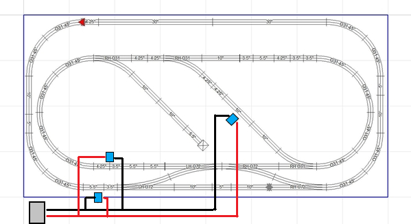
I realize that this is a earlier description of your track layout, but schematically correct. Its not that there are shorts, but just too high of a draw at times. Wire your power in this method from the DCS explorer.
You fine Sir win the prize!
Resolved.
I only have two lockons that I had setup across from each other on the outer and inner loop as you have pictured on the left of your diagram. I moved the inner loop lockon to the center of the reversing loop straightaway as you have pictured. I am only using the one 50 watt power supply plugged into the Explorer with banana plugs to the outer loop lockon and wire run from it to the center lockon connecting to the wire nuts. All switches are using track power and are working properly just in time for Game of thrones.
I really appreciate everyone’s input and I am looking forward to moving this build along finally


