As suspected and as Chuck had pointed out, two of the whisker tracks had too severe of a lead-in curve for the engines to negotiate, so I eliminated those two and now have 7 powered whiskers, plus one powered lead-in track and 4 non-powered sidings in the roundhouse/turntable area.
All of the whisker tracks are now permanently cut to length, screwed down, flush with the bridge track and programmed into the TT keypad and tested.
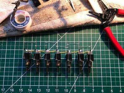
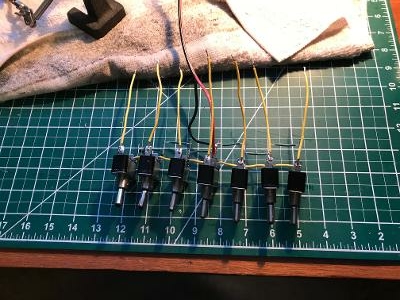
I went to work on the LED lighted switches so I can individually turn each whisker track on and off as needed, and soldered all the hot tabs together with small pieces of yellow wire. I then soldered a diode to each ground tab to reduce incoming voltage to the LED light. The switch is only rated for 12v and the incoming voltage will be 18v for command control, so I wanted to try and reduce the voltage just to the LED so the light would not prematurely burn out. The diodes are unidirectional, so it's critical that they be oriented correctly. I then soldered all the commons together by soldering green wires to all the diode legs. Brought track power in by soldering a 4' length of stranded red and black paired wire to the middle of all the hot and common wires - this wire is connected at the other end to a track distribution panel under the layout. Finally, soldered 5" long yellow pig tail wires to the remaining load tab on all the switches so I didn't have to solder underneath the layout - these are connected via crimps to each of the center rail wires on each whisker track.
The pics show the switch assembly before and after the power and pigtail wires were installed. There was a lot of cutting, stripping, twisting, tinning and soldering of a lot of small wires.
BTW, because I had ordered stainless Gargraves track, I used those male wire tabs to insert into each rail from underneath and they worked great. I don't think those will be coming loose anytime soon !
Inserted the switch assembly from the backside into the pre-drilled mounting holes in the layout edging and connected everything up and it works great. Only issue is I somehow got the switches installed upside down so they light up in the down switch position instead of up (which is what I like) but I'll live with it. Also, I had drilled 9 holes for whisker tracks so two of them are now just dummy switches that don't do anything.


