


Moonman, Everything you've said makes sense and is how one would expect things to work, It is exactly what I would say had I not stuck a meter on mine, or tore it apart to see what's inside it... but it is not how the Z1000 actually works. The Z1000, and associated Z-Controller, is a very strange transformer.
Moonman posted:Dan,
The MTH Z-1000 provides about 5.5amps. You can connect the switch power feed to the 14v ACC screws on the brick (transformer) . They are marked + -.
Yes, you could, if you are not using the other output of the brick connected to a Z-Controller.
I believe it is accepted practice to use only the hot to the switch and let the switch use the track common. That's ok.
It is fine, assuming your supplies are in phase... however it is impossible to put the output of the Accessory terminals in phase with the posts on the Z-controller. (without changing internal wiring)
Then connect the red (hot) and black from the controller posts to the track center and outside rails.
If you do this, the switches will not work. They are only going to see about 6 volts of power. See photo below.
However, the switch coils will use up some amperage for the train supply from the controller outputs.
As long as you use track power from the controller and not directly from the barrel jack all will be ok.
Actually the opposite of this is true. If you were to run the track for a command control environment directly from the 20VAC output of the Z1000, that connection IS in phase with the 14V accessory output, and you would have no problems at all...(well except for possibly damaging Lionel product that recommends against 20 volts on the track.)
I am not a fan of the breakers. They are thermal breakers and usually trip at about 200% of rating. 5 amp would be the highest I would use. It still may not kick fast enough.
Yes, but it is better than the internal breaker on a post war KW. If you want really good protection, you probably want the PSX-AC but at $50 for that, a five amp breaker that trips around 10 amps for $1.50 is a better over all solution for most folks. Your breakers are there primarily to protect your transformers (keep them from catching on fire) and to protect your layout wiring. A good electronic breaker may also help protect wiring inside engines and cars, but only somewhat. Even the fantastic breakers in a PH180 are not fast enough to protect a direct short across internal components.
The Z-1000 has a breaker in the controller for track power. use an in-line fuse for the ACC power to switches. The newer blade type are easier to source and can be had in low amperage values. Take note that the directions instruct one to unplug power from source for the Z-1000 to reset after it kicks.
No, the Z-Controller does not have a breaker or fuse of any kind inside it. The only breaker is the one in the Z1000 brick. this is on the common side and connected to both the common of the accessory post, and the common on the barrel jack for the Z-Controller. The controller flips this around, do the breaker is on the red post side of the circuit after the controller. In effect, track common (outside rail) is unfused with Accessory hot, so if you used the method suggested above to power the switches, not only would they not have enough power, but they would also have absolutely no circuit protection.
Things are still simple. Just hook up the Z-1000. Leave the old stuff for decorations.
As a note, if you used a 6 amp breaker on the U post output of the KW, it is providing exactly the same output as a Z1000, and is exactly as safe. If you then placed a breaker on the A and B post outputs as well it is actually much safer than the Z1000. A transformer is an amazingly simple device with very little that can go wrong with it. I would recommend checking that all the internal wiring is in good shape before using a post war transformer, but once you have it in good shape there is nothing that makes another transformer any better. (added breakers assumed.)
Just make a test loop on the floor with a couple of switches and test it.
Here is what the switch would see connected to the hot of the accessory post, with common from the track:
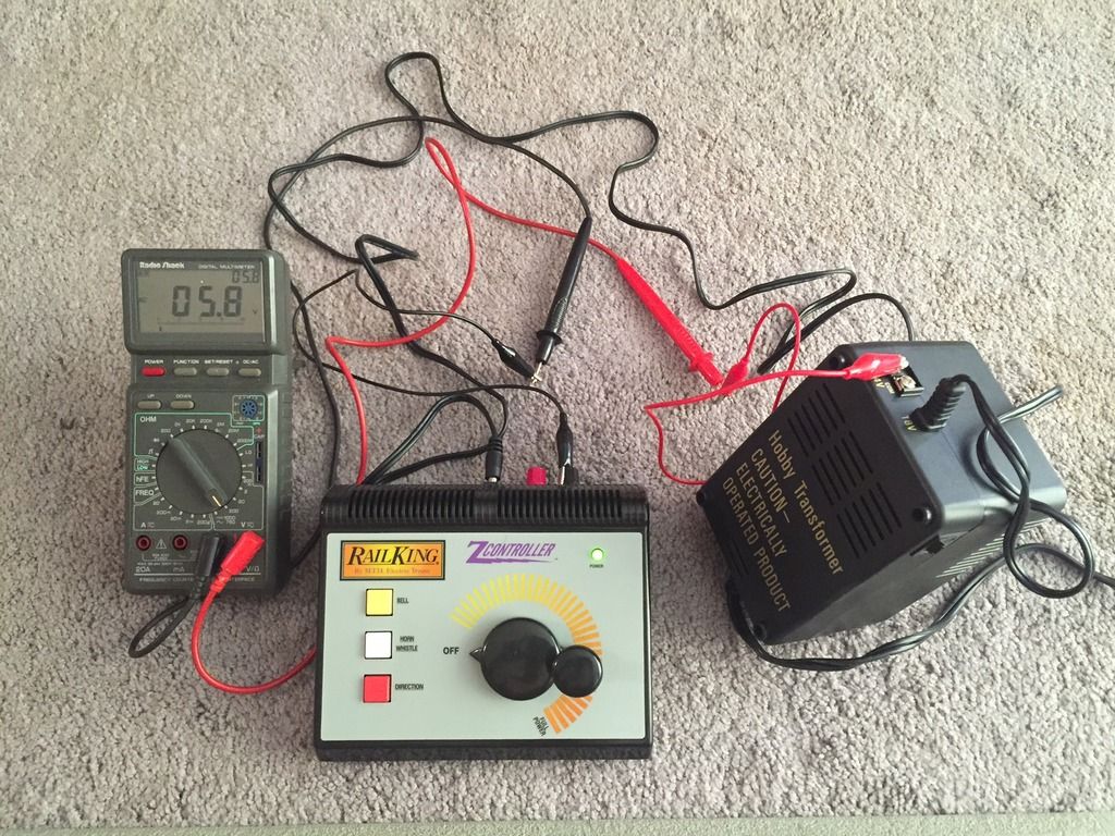
Here is the Z controller common connected to the Accessory common with a volt meter:
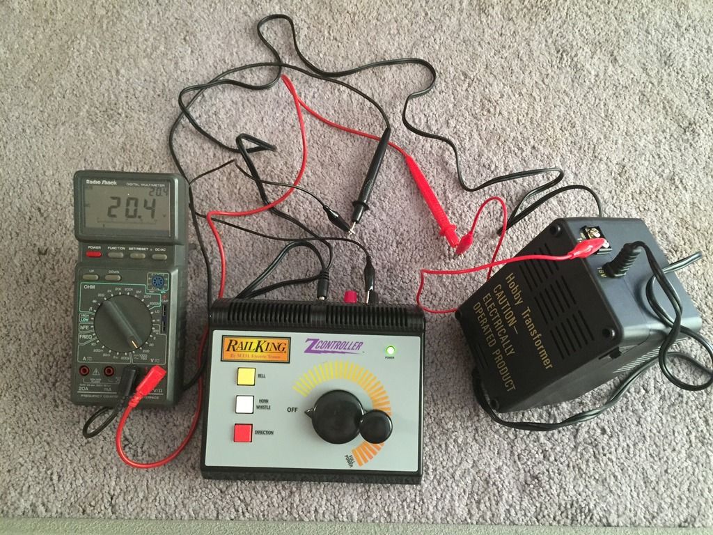
And here is what you get... with the Accessory post common and the red post, as these are the same connection with the controller between. As you turn up the throttle, the voltage drops.
All in all I recommend against using both the accessory and Z-Controller outputs, as doing this safely is a big pain. Simply using a second transformer, since Dan already has one, is a better solution. If it were my set up, I would actually use the KW to run the trains and the Z1000 for the accessories, as I like the feel of the KW better and it would allow for two tracks, but I explained above based on the Idea that Dan preferred the Z-controller as a train throttle. The bell button is a nice feature, though you can get bell buttons for post-war transformers.
JGL
