Hello all. Finally time for wiring! I’ll try to keep this as brief, but concise as possible. A few photos that I’ve included may help to visualize my questions better.
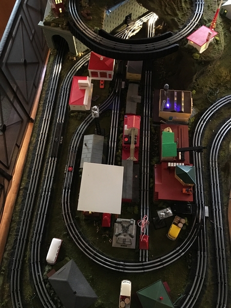
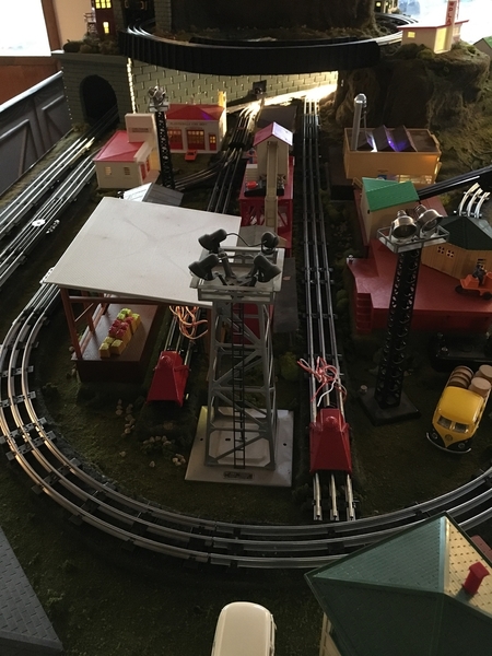
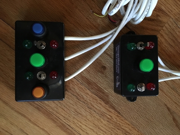
I have two unconnected loops of O36 tubular, that have bus fed & soldered-on drops for power every six or so sections. All conventional locomotives, a KW powers them. A 1033 provides fixed accessory voltage. The inside loop has four bootstrap fixed voltage powered O22 switches that create one curved siding with a short spur, and also one longer spur. The switches will be actuated in pairs by TinMan’s lovely dual controllers, one pair of switches with the ‘normal’ controller, and one switch pair’s controller fitted with the additional ‘spur control’ feature. For those unfamiliar, the spur controller has separate buttons that will power a center rail insulated spur section of track when they’re pushed. It’s much the same as having a toggle switch to create separately powered blocks, just in a nice tidy package
Now for the questions...
1. Will a UCS uncouple/dump track section that’s fed by it’s own independent fixed voltage source continue to be operational when that spur’s track power is not on?
2. Is an O22’s center rail able to be isolated by fiber pin on its straight section’s center rail to create a block, or can an O22 only be isolated on its curved section? I ask this because I’d like the ability to park & then power off one loco on to the shorter spur that’s on the photo’s left, (under the shed) while still having the siding loop that encircles it powered for running a different loco. I’m assuming that I would need to electrically isolate the short spur section through center rail of the the switch’s straight section to facilitate this.
3. The inner mainline loop & it’s siding will run clockwise. Will having the switch that ends where the siding meets the left spur be powered by fixed voltage screw up either the operation of the siding or it’s spur when I have the siding’s track power switched off? Should I NOT supply this switch with fixed voltage, but rather track voltage? I’d like to have a consist parked on the siding, with the siding’s track powered off, and be able run a small loco for switching duties up from the bottom of the left spur (under the shed) out to the mainline loop & it’s neighboring spur on the right. Is this even possible?
4. Suggestions please! What position on the layout would be the best place to use the switch controllers that I already have? The obvious choice would be the right side spur to receive one channel of the switch controller with the built in spur control, but would a simple toggle to control the track power be better here, leaving both channels of the switch controller with spur function open for somewhere else? Should I use both channels of the spur control switch

 for the two right hand switches on either end of the siding? Should I use the the regular switch controller for the two left hand switches at the top of the mainline, or put the spur controllers here? This is where my total lack of knowledge in creating electrical blocks shows through!
This got kind of long, my apologies...
Any hints or help is greatly appreciated!
Tom


