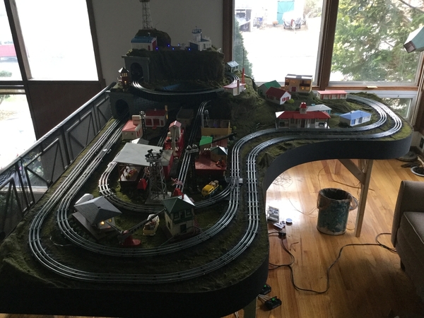
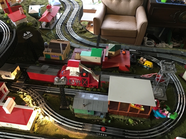
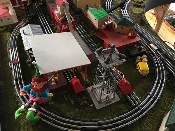
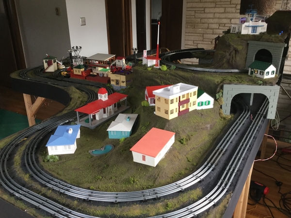
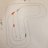
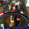
Thanks for the replies, and kind words! This is my first layout attempt. With the help of my six year old, we’ve created a track plan to help describe what I’m after. Using her idea of color coding, we colored the switches blue and orange for the top two left hand switches, and the right hand switches that create the inner siding loop are red & green. Also some other pictures below to perhaps help visualize what I’m attempting.
Dan, number one’s answer was incredibly concise! Allow me to ask one more questions along these lines...Is it ok to use a UCS section as the first piece of track connected to the turnout (blue) that creates the right side spur?
Dan & JD.. for question #2, since I am using TinMan’s own bootstrap that does indeed power both the switch AND it’s track, would I still need to have a metal pin on one of the switch’s legs for track power?
For questions #3 & 4, I’ll try my best to explain... My layout plan initially had only the two parallel spurs coming off of the blue and orange left hand switches at the top; this is where I was going to use the double spur switch controller. Since I can’t leave well enough alone, I bought the two right hand switches (red & green) that make up the curved inner siding. This is where I’m getting confused on how to best utilize the spur controller’s capabilities. I guess my original question is what would be the best place to use the spur switch controller, and the standard switch controller. Dan, you said use the spur controller for both sides of the siding. Would that mean I’d have to have both of the controller’s power buttons turned on when operating a train on the siding, or would one of the controller’s power buttons suffice? Would it be easiest to work the siding in that way, and then have the short spur below the red switch powered by its own dedicated toggle to supply track power, and have it be isolated from the red switch? Does it appear to you that a separate dedicated track power toggle, on the long right side spur that extends from the blue switch, would be best for there as well?
To summarize, top two switches (orange & blue LH) use the standard switch controller. Use the spur controller to actuate the red and green RH switches of the siding. Have the longer right, and short lower left spurs be powered by their own independent toggles, and electrically insulated from their nearest switch; thereby creating blocks for parking locomotives. Does this sound correct and plausible?
Sorry for the multiple questions, I want to get this right the first time!
Cheers!


