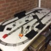
so, I’ve settled on a track layout for my O27 “door layout”
The lighted bumpers came from eBay and have the benefit of indicating power status in the sidings!
I’m going to fix the track down now, and look at the wiring in more detail. It can be made to run from a single power connection, but that clearly isn’t the right approach. The switches are the “dead block” type, although the x-crossing appears to have the effect of powering the associated siding from the reversing loop, without reference to the entry switch...
so, a couple of questions.
1) the two uncoupler tracks (in the passing loop) appear to trip the power supply. I suspect that this is because there are two many switches and accessories together, resulting in too much accumulated voltage drop and/or resistance. It looks as though a power connection between the two, would solve this?
2) I’d like to fit some sort of anti-derail precaution, especially on the lower straight. I’ve seen a suggestion to fit an isolating pin on the straight exit, one joint from the switch, do that this area is only live when the switch is set that way? This sounds good, any comments?
3) I have an automatic crossing gate. The “weight trigger” looks to fiddly, and I’ve seen a thread here on the forum about running it from an insulated rail. I’ll look into that.
4) I have a Dwarf Ground Signal. I’m wondering what use to make of this.


