


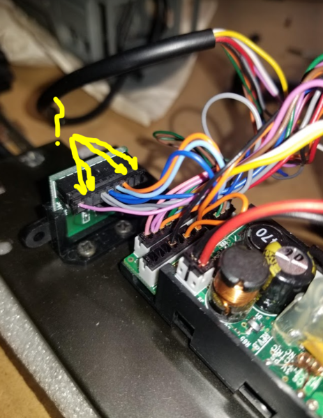
@Lou1985: See photo attached. The tender harness is a typical 10 pin, and I'm still really stumped on that secondary tender connector inside the tender. To be fair, this board was not original with the S1, it is stolen from a RK diesel. So maybe I'm supposed to have a separate 10pin-10pin Female-female tender harness that goes from the loco connector, through the tender to the vertical connector, then somehow that feeds the board? The tender cable / harness you see here WAS already pre-wired to that connector, so It gets used somehow.

I've played around quite a bit with the boards and wiring and I've got some more things figured out, but that odd 10 pin connector mounted vertically in the tender is still confusing me.
I have found the connector that attaches the PS2 board to the MUX board in the tender, and I can sort of trace what wire do what based on the pinouts of the PS2 board. There's a purple wire that runs through the tender harness to the loco and I'm thinking it has something to do with MUX board power or something, since it doesn't seem to be right for the "Normal" PS2 outputs.
On the engine side, I figure out that there are too may lights to be connected just to the RX MUX connector, and I realized I needed to install a secondary light distribution board (I had one sitting around). So I just need to figure out which wires I still need to add to the empty MUX pinouts and run them to the aux board, then I should have enough connectors for all my lights.
I also think that since this particular PS2 board was stolen from a RK diesel, there are several pinouts that I could / should connect from the PS2 to the tender MUX in order to make sure I can take advantage of all lights in the engine. (photo is my own aux board I had from another project, so colors and IDs don't really apply. I've got 4 wires I can use already (just need to plug them into the correct MUX pinouts) and one more location I can solder another wire to for 5 total jacks available.

For the lights, I can see (pretty sure these are right)

- Yellow connector with B&W wires : Marker lights in front of number boards (Grain of Wheat red LEDs)
- Blue connector with 2 black wires: Headlight
- Black connector with 4 black wires: Number board lights (mounted to the same bracket as the headlight, this was easy)
- Red connector with Purple & Brown wires: Smoke motor
- White / Olive Green Connector with Green & Gray wires : Smoke Heat element
- Black connector with Orange and Purple wires: Connects to Firebox and cab lights
- (Not shown in photos) Olive green connecter with black wires is another clear white LED with about a 10cm harness that I can't figure out where it goes. It's the same LED as the headlight. Can't find any holes in the loco shell that make sense for it. Is there some sort of beacon light or flasher? Or does it somehow go in the tender as a backup light or something?
I figure any of the connectors that don't have a mate mounted directly to the MUX RX board, then I can use the auxiliary light board. I just need to figure out where to add the pinouts to the empty MUX slots and then plug the correct connectors to the aux board.
There's a couple additional Overall photos attached, as well as this photo of the engine tether connector:

If anyone on this board has any photos of the complete S1 guts fully installed, it would be a huge help. But I know that's asking a lot.
Once I figure out all of the electrical connections, I'm going to set it all aside and paint the shells.
Thanks for everyone's help so far!


