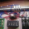
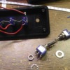
Next step is to modify my "Manual-Automatic" control section. I got rid of the green board which was used to sense the switch position via "RSC Lights" I don't have enough inputs to use this so it will be replaced with the compensation box. (Reduced voltage) Track power 1 has to be changed to put out both full and reduced voltage via a double pole relay. This also means the first switch has to be changed to a double pole switch. My plan is to use "Track Power 1" as the mainline power. This also gave me a chance to relocate the relays to a better position. With these changes, Track power 2 and 3 will be reduced voltage (throughway, and side) Track power 4 (spur) will be full voltage. This is the same as my wall layout.
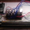
By eliminating the track switch position sense, it made my terminal block shorter.
The reduced voltage will be fed into the main PLC unit. That unit will also have to be modified for these changes.
Mike


