


A few weeks ago, Peter (@Buco) needed ideas to reduce his transformer output voltage. Out of total curiosity I went to the bench and played with some components to accomplish the task.
Then things escalated real fast and got out of hand….
This is a build-it-yourself conventional train controller and lamp dimmer for AC toy trains based on the inexpensive HiLetgo 50 – 220 VAC Motor Speed Control Module Dimmer Speed Regulator sold on Amazon for $6.19. With modifications described below, the device can output voltage in the 0 to 18 VAC RMS range.

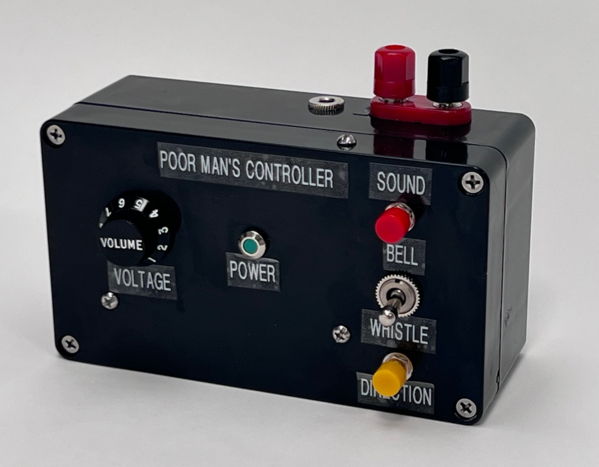
Modifying the unit and adding bell/whistle circuitry, switches, connectors and enclosure results in the following:
The target audience are electronic tinkerers and those who are pretty savvy with building and soldering. This project is not a substitute for a DCS or Legacy controller.
As previously mentioned, this project was motivated by a recent posting by Peter (@Buco) who required an AC voltage level lower than provided by his MTH Z4000 transformer running at 50 Hz. The issue was that the MTH PS1 engines--while in neutral-- require an intermediate voltage level in the range of 6 to 7.5 VAC that allows special features to be programmed into the engine. The throttle is rocked between high voltage and the 6-to-7.5 VAC range to produce a series of clinks and clanks to represent different programmable features. Peter was having difficulty achieving the lower voltages running his MTH 4000 at 50 Hz. (This is not a usual problem!) Both the Z4000 and ZW typically do not provide an output below 6 VAC. With modifications described below, the HiLetgo device allows the voltage to be adjusted low enough to ensure the ability to program MTH PS1 engines. The other obvious application is for light dimming on the layout. (I have not tested it for powering accessories.)
Voltage Control Techniques. As a way of technical background to this project, it should first be mentioned that there are two commonly used voltage control methods used in AC toy train transformers and controllers for conventional operation. One method is using amplitude control; the other is called phase control switching.
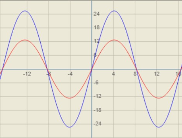
Amplitude Control. As depicted in the figure below, the transformer output voltage is determined by the amplitude of a 60 Hz (or 50 Hz overseas) sine wave. The blue trace is 18 VAC RMS (25.4 V-Peak) and while the red trace represents 9 VAC RMS (12.7 V-Peak). (Unless stated otherwise, all further references to VAC are assumed to be RMS voltages.)
Here is the actual waveform from a Lionel ZW transformer for 9 VAC (10v/div; 2ms/div).

And here is the waveform at 9 VAC from the MTH Z4000:
Amplitude voltage control has been the method of voltage control for toy trains for over a century!
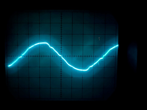
Phase Control Switching. In this method, a sold-state device called a triac is used to chop off part of the sine wave to achieve lower RMS voltages. This is depicted below.

The full waveform represents 18 VAC. To achieve 9 VAC, as an example, the triac is turned on slightly more than a third of the time. [See reference at end of this posting for calculation.] The Lionel CW80 and MTH Z Controller uses this method of voltage control. For higher voltages, the triac stays on longer; for lower voltages, the triac duration is less.
Here is the actual waveform for the Lionel CW80 set for 9 VAC (10 volts/div; 2ms/div):

Here is the waveform for the MTH Z Controller also set for 9 VAC:

Looking at these choppy waveforms, it may seem intuitive that not all toy trains would work so well but, in fact, many old and new trains function just fine!
An inherent feature of these controllers is that a voltage output lower than those of the Z4000 or ZW is achievable. The CW80 and Z controllers have a range from 0 to 18 VAC.
Commercial Light Dimmers and Motor Controllers. It turns out that the vast majority of home light dimmers and industrial motor controllers use this phase control switching method because of lower cost and smaller size of components compared to amplitude control methods.
From time to time, the idea has been raised in train forums on using lamp and motor dimmers to control model trains using alternating current. The problem is that virtually none of them are designed to work with the low voltages (0 to 18 VAC) required toy train devices.
To better explain the issue, it is worthwhile to examine the inner working of the dimmer.
The $6.19 HiLetgo product uses the phase control switching method to perform voltage control but at 110 or 220 VAC rather than the 0 – 18 VAC range needed for toy trains and lighting. Here is the schematic:
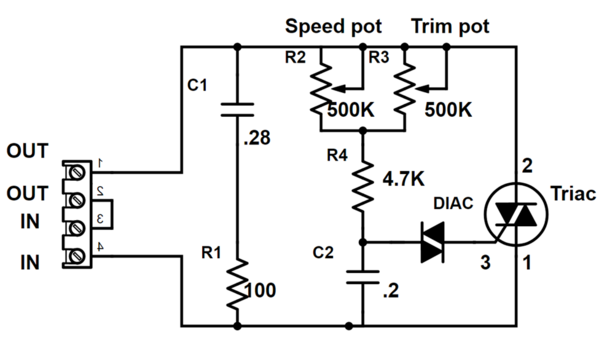
In operation, the speed pot sets the point on the sine-wave cycle where the triac switches to the on state. The key component is actually the diac device which is used to send a trigger signal for the triac to turn on. Most dimmers and motor controls employ the diac with the triac. The problem using this type of circuit design for toy trains is that the diac minimum trigger voltage is typically 32 volts. Thus, applying 18 volts to the type of circuit will produce no output.
The solution for operating at low voltages is to replace the diac with a trigger component that operates at much a lower voltage. The secret ingredient to make these circuits applicable for toy train use is a component called a bilateral switch to replace the diac.
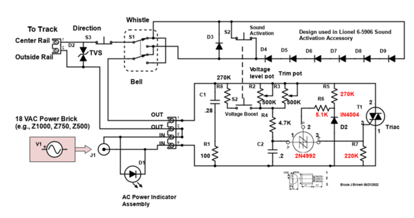
After much experimentation and trial and error on the bench, here is the schematic of the modified HiLetgo product that will operate in the 0 to 18 VAC range.
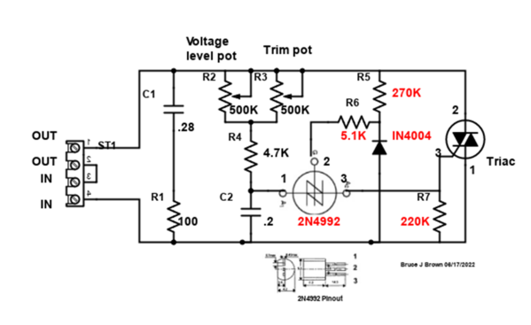
The new components are shown with red ID’s. The 2N4992 is the Bilateral switch which triggers the triac. All the additional components are used to provide symmetrical switching to ensure the tops and bottoms of the waveform have the same peak levels to produce an output with negligible DC component. (A 2N4991 bilateral switch will also work as a substitute for the 2N4992.)
Eighteen (18) VAC is supplied to the input terminals from a transformer brick such as a Z1000, Z750 or Z500. The output terminals are attached to the center and outer rail of the track or to lamps that require AC voltage.
The only adjustment necessary is the setting of the trim pot to have the voltage swing from 0 to 18 VAC over the full rotation of the voltage level pot rather than just a small area of rotation. This will make it easier to control the desired output voltage.
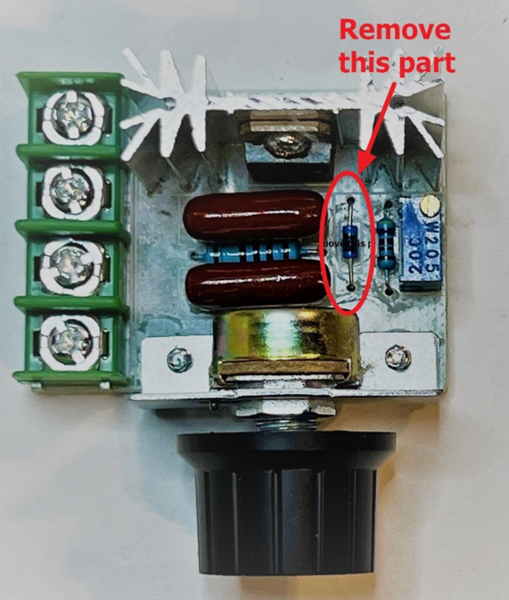
Modification Process. The first step in the modification is to remove the diac.
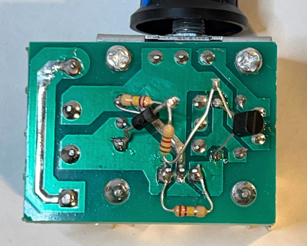
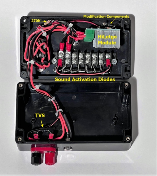
I originally mounted the extra components to a separate PCB prototype board but found it much easier to solder the components directly to the back of the HiLetgo printed circuit board with the ends of the parts elevated. Here is the result:
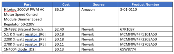
Here is the parts list:
Sound Activation. To complete the design, a sound activation capability is added—consisting of 7 diodes mounted on a terminal barrier strip-- to provide the whistle and bell function. This is accomplished using the Lionel design employed in their 6-5906 sound activation unit. Lionel uses 6 amp diodes.

In the Poor Man’s Controller, a double-pole double-throw (DPDT) switch is used to reverse leads on the sound activation circuit to either put a plus DC voltage on the track to initiate the whistle, or a negative DC voltage to sound the bell. The inherent problem with this sound activation technique is a loss in AC voltage through the diodes. To partially compensate the loss of voltage through the diodes, a voltage boost/increase feature has been included which is initiated when the sound button is pressed. This boost capability is adequate, but not perfect. When the controller output voltage is relatively low, sound activation will speed up the engine; for higher output voltages, the engine will slow down.
The Z Controller and Lionel CW80 handle sound activation differently. To create a DC offset, yet keep the AC output constant, a more sophisticated triac phase control is used. For the whistle command, for example, the triac stays on longer for the top portion of the sine wave cycle, and less for the bottom. This creates a positive DC voltage while keeping the total on-time of the triac the same as before the whistle button is pressed. For this Poor Man’s unit, it would have required much additional circuitry to accomplish the sound activation totally through phase control. That type of whistle/bell generation is beyond the scope of this project.
Protection. A voltage clamping TVS semiconductor is used at the output as extra insurance to prevent any higher voltage switching transients from reaching the track. A breaker can be used at the output for even more protection but a breaker already exists within the 18 VAC power brick.
Below is the parts list. All parts, except the TVS, are mostly Amazon Prime to reduce shipping costs and selected by cost and item availability. (The downside of ordering from Amazon is that sometimes you are getting more quantity of parts than you actually need.)

As you can readily see, the cost of the project is not so much in the actual electronic components but rather in the mechanical items such as switches, case, and connectors. (A major challenge was finding less costly momentary push button and normally-closed switches that can handle at least 6 amps. These are used for the direction and sound activation functions.) Most of the internal connections use #18 speaker wire. The existing unmarked knob provided from HiLetgo is replaced using an electric guitar volume knob to make it easier to correlate output voltage with the pot position setting.
The internal layout of the completed project is shown below.
Adjustment. There always must be a load, even just a lightbulb, for the controller to produce a variable output at its terminals. With the voltage control pot set at the middle (“5”), adjust the blue trim pot on the HiLetgo board for an output of approximately 6-7 VAC and near zero output with the voltage control turned fully counter-clockwise. Most of the train operation will occur in the “6” to “10” range.
Here is the output for at a 9 VAC setting. (10 volts/div; 2ms/div). It is virtually identical to that of the MTH Z Controller and CW80.

As previously mentioned, this controller has not been tested with any accessories, although it certainly should be able to work with some of them.
Recognition. I would not have done this project had Peter @Buco not asked the question about attaining a lower transformer voltage. Thanks Peter. I hope all the above addresses your question!
Here is a video of the controller in operation.
https://www.youtube.com/watch?v=3xS8a-9pwXI
=======================
Reference for determining relationship of Vrms to triac on-time:

Source: http://educypedia.karadimov.info/library/an1003.pdf
Conduction angle is the triac on-time. 180 degrees is equivalent to a half-cycle or 8.3 msec for a 60 Hz sine wave.


