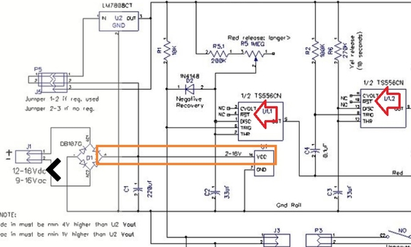
Regarding the latest schematic in this thread:
1) The output of the bridge rectifier directly supplies the 555 timer IC supply voltage (in orange). If you supply 16V AC, that will generate over 20V DC at the IC chip which exceeds its operating voltage range. I suggest you power the IC from the 8V DC 7808 output.
2) The "reset" inputs to both 555 timers is shown as No-Connect in this version of the schematic (they were connected to the supply voltage (as it should be) in at least one previous schematic you posted.
A floating or disconnected Reset input can cause flakey unexpected behaviors. I also notice earlier schematics show the LM556 bipolar version of the dual 555 while the most recent schematic shows the lower-power TS556 CMOS version. For example, regarding the typical Reset current the CMOS version requires only 10 picoAmps (typical) to trigger and inhibit any timer operation. That's >10,000 times less current than the 0.1 milliAmps for the bipolar version. You can just about generate 10 picoAmps by staring intently at a circuit! ![]() In other words, connect the Reset pins to the supply voltage!
In other words, connect the Reset pins to the supply voltage!


