Clearly you're going for a speed record to get a board into production! ![]()
As you know, you need to give time for the designer to waffle and/or add bells and whistles.
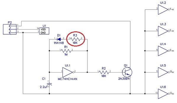
Anyway, IF a board is made, I suggest adding R3. This would make the green LED blink OFF longer (it is kind of hard to see in the original design and not visible in the original video). It is visible in following video which has R3 added per modified schematic below. It does not change the performance but is visually more appealing/comforting to see the blinking green light. Note that the 10K value is already used so it's not a "new" part. From assembly rendering it looks like it could be placed alongside existing resistors without adding to board size.
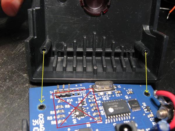
The other issue is there may be interference from the mounting posts on the top of the case.
It seems to me if the 3-pin J2 installed from the solder-side of the PCB (and soldered on the component-side), the board will hit the left post from the case lid in the above photo. The red box area is the footprint of how I did it. I realize the choice of 0.1" header/socket influences orientation.


