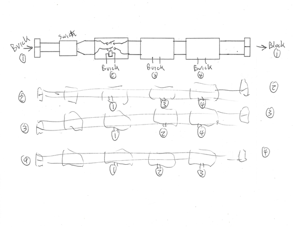
Here is a possible circuit explaining the 12 relays. From the photo each column covers one power channel. The brick power comes in at the bottom then flows through the switch and three relays in series. All the coil wires sneak through holes to the back. Clearly the magic happens on the other side of the board. My surmise is the relays are driven by the three "other" bricks in each channel.
I am still trying to sort out the terminal strip at the top. Also the red wire on the right side may mean the relay coils are connected to the track sections instead of locally on the back of the board.
Cam


