What I wanted to show is how the sense relays and relay logic* could be used for an interlock chain. In logic terms it is and AND gate. Outputs are enabled if Brick 1 is on AND Brick 2 is on AND Brick 3 is on AND Brick 4 is on.
Since the control relays interrupt the power to the track, the bricks are still powered. If you have a pilot light on the output of each brick you will see which ones that are on.
The sense relays could be replaced with simple sense circuits on each brick. Optocouplers would allow the logic be done using low voltage DC that drives a single relay which in turn drives the power relays or with suitable output drive could control the power relays directly. There are endless approaches here.
Controlling the 120V power only requires one control relay and it operates at lower current. You do need to deal with 120V though. There are prepackaged relays from controlling appliances so you don't have to deal with 120V - but I don't know if the right specs would be available. Driving four fully loaded 180W bricks would be 720W. That is 6 Amps on the AC side. If you don't expect to use that much on average you could use a 5 Amp relay but you'd need a circuit breaker to protect the relay contacts.
With the 120V approach the system will latch in the off state when it shuts down. Also it will power up in the off state so you do need a Start switch after power up or to reset. If you have a power failure the system will be off when power returns until you press the Start switch - this is an added safety feature.
If you start using normally closed contacts you can avoid relays being constantly energized. However you will lose the fail safe aspect of the relay power supply failing. But if you stipulate the relay power supply will be on you can take the NC approach.
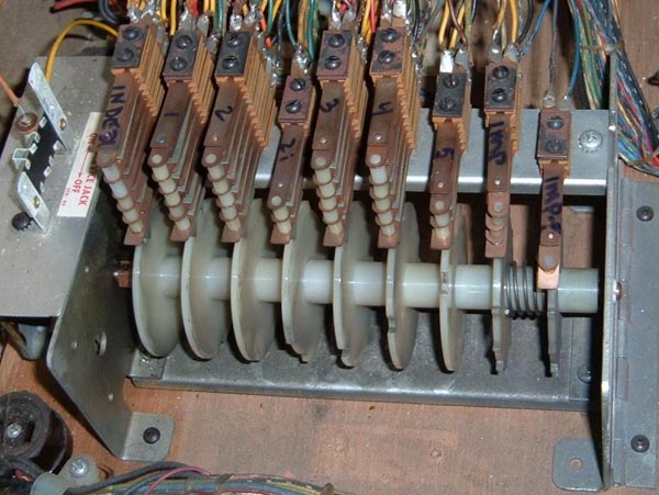
*Relay logic - I have an EM (electro-mechanical) Space Odyssey pinball machine from 1976. EM pinball machines are all relays, switches and solenoids. These machines have a score motor, essentially a washing machine timer switch on steroids, that turns until certain conditions are met. The score motor is what makes the score roll up multiple steps on one switch closure. Mine has a common problem where the score motor does not stop running. Debugging this is no easy task. The schematic is a ladder diagram (one way of showing relay logic) - it is 4 feet wide.


