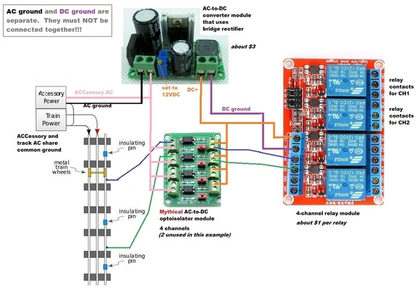
stan2004 posted:As Dave says, opto isolation can be a remarkably effective and inexpensive solution to noise issues. From my previous post I'm still not clear on exactly what problem is being solved. In any case, refer to this recent thread from which I copied the following:
In the other thread I was proposing changes to a $2 (4-channel) DC-input optocoupler module to make it compatible with AC O-gauge. I suggested a bridge rectifier and a capacitor. And there they are in the OIB-8! Member rtr12 might be making a circuit board that would bring the cost per channel way down relative to the OIB-8 price. In any case, unless you already have a box of AC coil relays looking for gainful employment, you simply can't beat the price/value of the eBay DC relay modules (about $1 per relay). They have trigger buffers so that you don't directly drive the relay coil. Hence you only need a fraction of the ground trigger current flowing thru the insulated-rail section - just a few mA rather than tens of mA. In general, reducing the trigger current requirement gives you more options.
If optocoupler isolation for relays is something you're considering, you may want to tack on to the other thread if the focus of this thread is EMF.
There is an almost complete but "never tested" 4 channel version of a PCB using the PS2505-4 IC chip which accepts an AC input. Parts are ordered, but I don't have them and it will probably be a while (Aliexpress). Needless to say, no testing until parts get here and no sample PCBs have been ordered.
The circuit used for the PCB was the one discussed in the other thread that Stan linked to above and is similar to the 'ready made board' in the center of the top picture above. It doesn't have the bridge rectifier like the OIB-8 in the second picture above.
If anyone is interested I can post the Diptrace files of what I have so far. The PCB layout file needs some additional labeling and possibly some further arrangement of the components. And, as stated earlier it is 'completely untested'. Posting the files to the other thread would be more appropriate, so that's where I would put them. That's where I was going to post them after they are tested and working.


