


Black and Red are power to the gate. Note that Red is hooked to the center rail and Black to the outside rail for in this case a full 18 volts.
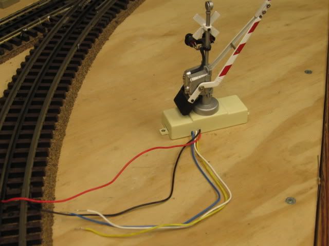
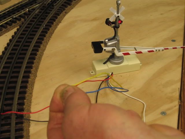
Touch the Blue and white together and the gate will go up or stay up. It will remain in the up position.
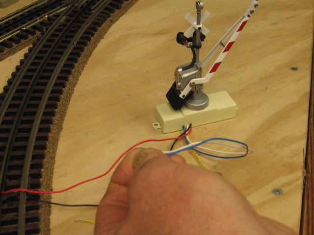
Touch the Blue and yellow together and the gate will go down and stay down. It will remain in the down postion.
My take on this but I could be wrong and by the diagram am:
Blue is Common
White is Normally Open (NO in the energize state)
Yellow is Normally Closed (NC in the energize state)
Your relay should have at least (5) pins My guess is that it has (8) (2) pins are for coil power. and there are (2) sets of NC/COM/NO contacts that you can use.

Pin (2) would be track power center rail
Pin (7) would be track power via the isolated rail section
Pin (8) COM would be the Blue wire
Pin (6) NO would be the White wire
Pin (5) NC would be the Yellow wire
If I'm wrong you would reverse White and Yellow wires.
SRE 202D, 12VDC, 5A 240 VAC, 5A 28 VDC and has 7 pins. This information indicates that the relay coil is designed for 12 volts DC, and that the NC/COM/NO contacts are rated for 5 amps 240 volts AC or 5amps 28 Volts DC. I'm not sure this relay will work. To energize the coil we would apply track voltage (AC) via the isolated rail section and Track power. My take is it should be an AC coil at or as close to the applied voltage as possible, most likely 12 or 24 volt AC
