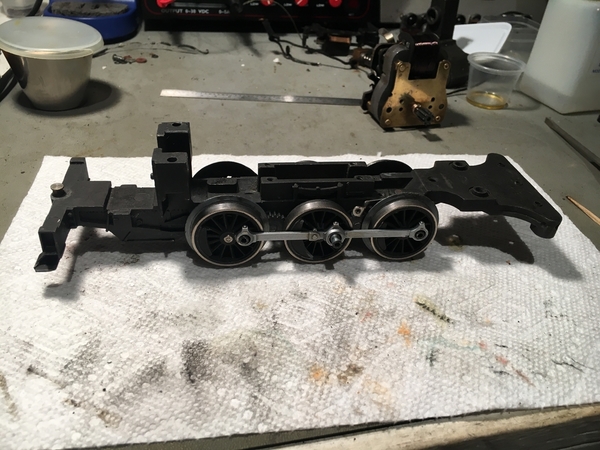
To reassemble the engine portion of a 227 family of locomotives requires that the process be done in a particular sequence to get all the parts to fit properly. To avoid many false starts, I took the time to write out the sequence. I assembled a locomotive today and used this experience to check out my written assembly instructions. The process worked well and I typed them up and am sharing this procedure with others who work on these locomotives.
Engine Assembly Procedures, Prewar semi-scale and scale 0-6-0 switchers, 227, 228, 230, 231, 232, 233, and 701
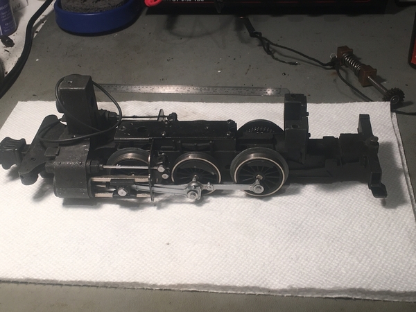
Complete disassemble of the engine is required for some maintenance procedures including wheel changes, stub shaft and idler gear change, and complete cleaning and lubrication of the locomotive. In this document the term “engine” refers to the frame with the wheels, rods, valve gear and steam chest. In this family of Lionel prewar switchers, a specific sequence of assembly has to be followed to get all the pieces properly reinstalled.
If the wheels have been removed, the right hand (gear side) eccentric rod cam follower, 227-43, must be installed as the wheel is pressed on. It is not possible to install this part after the wheels are pressed into place.
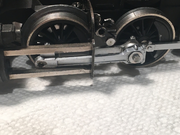
Install the right, 227-53, and left, 227-54, side rods with shoulder screws, 227-55, and flat washers, 011-24. Apply a ½ drop of medium weight synthetic oil to the crank pins prior to installing the side rods. The side rods should be installed with the simulated oil cups facing up the articulated rod joint to the rear of center driver. The side rod screws may be tightened with a 1/8” hex nut driver. Do not over tighten.
Install both current collector insulators, 227-48, with 4-36 X ¼ RHMS, Phillips drive. Install the left hand eccentric rod cam follower, 227-60 on the inside of the front left wheel.
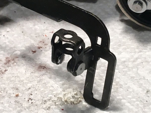
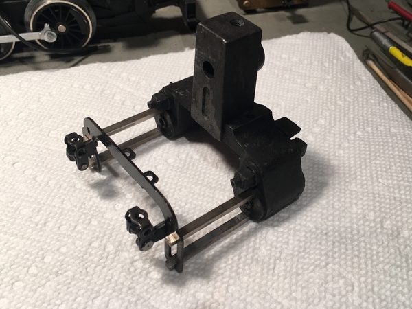
The valve gear support assembly, 227-81, should be built up next. The valve gear support is frequently found with bends in it. Prior to assembly these bends should be removed as best as is possible. I wipe down all the steel parts with a black phosphate finish with Tri Flow to give some additional protection from corrosion. Assemble the valve gear support 227-61 and the valve gear bearing assembly, right hand, 227-62, and left hand, 227-65, using shoulder screws, 227-67. The valve gear bearing assemblies should over hang to the inside with the U shaped opening down. The shoulder screws may be tightened with a 5/32” hex nut driver. Apply ¼ drop of light synthetic oil at the four swivel points. The bearing assemblies should move freely.
Run the super flex wire from the front coupler through the hole in the coupler swivel bracket and then through the hole in the frame behind the steam chest. This step does not apply to models 230, 231, and 701.
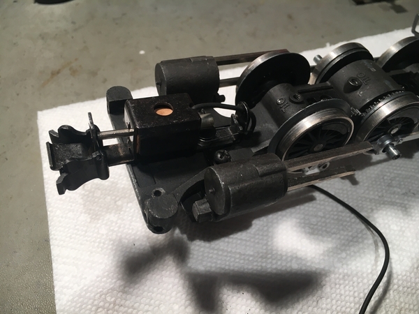
The four cross head guides will need to fit properly into the four notches on the valve gear support assembly when these two parts are installed on the frame. These parts should be test fit at this point and any necessary adjustments made. Extreme care should be used in adjusting the crosshead guides, as I am not aware of a repair technique for repairing the crosshead guide if it is broken off the steam chest. Run a 6-32 tap, held in the fingers, not a tap wrench, into the three tapped holes in the steam chest. This is to clean out any dirt in the threads. This process should not remove any metal. Install the steam chest assembly, 227-72, and the automatic coupler assembly, 227-73, onto the frame with two 6-32 X ½ RHMS, Phillips drive and two #6 split lock washers, 2-111. Leave these two screws about two turns loose.
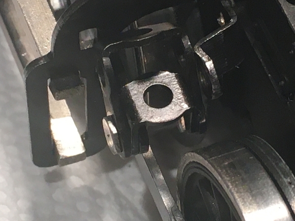
Install the valve gear support assembly, 227-81, on the frame using two 4-36 X ¼ RHMS Phillips drive. The mounting tabs should extend forward. Install the screws loosely. Ensure that the tabs on the right and left eccentric rod cam followers are inboard of the valve gear bearing assembly. Also ensure that the two U shaped yokes on the valve gear bearing assembly are free to move and are facing up leaving space below them for the side rods to move in and out of as the wheels rotate.
Work the crosshead guides on the stem chest into the slots on the valve gear support assembly. After the cross head guides are in their proper place in the valve gear support assembly, the steam chest and valve gear support assembly screws should be tightened.
Install the drive rods, right side, 227-98 and left side, 227-71, by inserting the crank pin ends (rear) through the front side of the slots in the valve gear support assembly. The part numbers cast into the rods may not match the part numbers given above. Ensure that the simulated oil cups are facing up. Apply a ½ drop of medium weight synthetic oil to the crank pins prior to installing the drive rods. Insert the hole in the rear end of the drive rod on to the crank pin on the center wheels. Install side rod screws, 227-55 and washers, 011-24. The drive rod screws may be tightened with a 1/8” hex nut driver. Do not over tighten.
Install the valve rods, 227-87, with the simulated oil cup facing up, through the slot in the valve gear bearing assembly and into the holes in the steam chest. Secure these in place using the long shoulder screw, 227-88, which passes through the valve gear bearing assembly and screws into the eccentric rod cam follower. This same procedure is required on both sides of the locomotive. The shoulder screws may be tightened with a 5/32” hex nut driver. Ensure proper alignment of these parts prior to tightening the screw to avoid cross threading.
To install the cross head, 700E-239, rotate the drive wheels so that the crank pin is all the way rearward and at the same level as the axle. Apply ¼ drop of light synthetic oil on each of the following locations on the crosshead: upper sliding surface, lower sliding surface, and piston rod. Insert the piston rod in the hole in the steam chest and slide the crosshead rearward and align the holes in the cross head and the forward end of the drive rod. Install hex head shoulder screw, 700E-59C, and the washer, 763E-56, to retain the cross head to the drive rod. The crosshead screws may be tightened with a 3/16” hex nut driver. Repeat this process on the other side on the engine.
To oil the outboard axle bearings, with the engine upside down, apply three drop of medium weight synthetic oil to each outboard axles through the oil holes and lay the frame on its side to give this oil an opportunity to run down the axle and get into the bearings. Work the wheels back and forth to work the oil in. Repeat this process to oil the bearings on the other side of the engine. Install the three oil hole screws, which are 4-36 X 3/16 BHMS and fiber washer 97M-15 in the oil holes. Oil the center axle bearings from the top in the gearbox. Apply two drop of medium weight synthetic oil to the axle on each side of the worm wheel. Work the oil in by tipping the frame assembly while rotating the wheels.
At this point the worm gear cover, 227-68 and the worm gear cover gasket, 227-69 should be temporarily install using four 4-36 X 1/4 RHMS. The faux stamped sheet metal leaf springs on the cover are installed facing forward with the leaf springs facing down. This temporary installation is required to keep the tabs on the eccentric rod cam follower from lifting from the frame as the wheels turn. If they do lift it jams the wheels. The frame may now be rolled back and forth to ensure all the mechanism is working properly, freely and smoothly.


