Adrian! posted:Actually...since I wrote that tutorial up there so long ago, I've made a new decoder that spits the data out a UART at 9600 baud that you can collect with a term emulator. It's attached if anyone wants to play with it.
You need a MAX232 or something to go between the angry RS232 levels, and 3.3V FPGA levels and clock at 7.5M of course.
Here's a cute little movie going over everything in the tutorial basically and demoing this code:
Links for the hardware used to get the signal out of the track or the driver to put the signal into the track
Adrain
Good post, but I am missing something on how easy it was for you to capture the various DCS signals. In your attached video, it seemed it was very easy to capture the DCS signal on your scope w/o hitting the freeze frame button on the scope. Every time you sent a command from the handheld the DCS signal appeared on the scope automatically and stayed there. Can you provide a simplified description of how you accomplished this. I don't want to read the 0s & 1s on my PC, just want an easy way to capture and view on the scope.
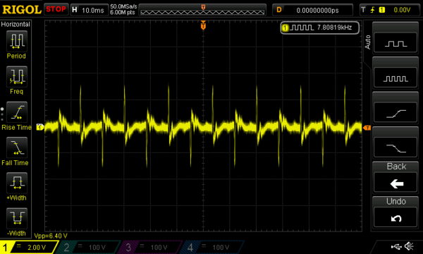
Also, I built the 4 stage butterworth filter you described and when viewing on a scope the 18v track AC is not completely flat as viewed in your video. Mine looks like the picture below. What else do I need to do to flatten out the AC track voltage signal.
Sorry for the novice questions.
Thanks,
Bob D


