rtr12 posted:...
I can do a little Arduino programming (with a lot of looking up syntax, libraries, etc.), but I am also somewhat fascinated with the IC chip methods and creating circuits with them. I'd like to learn more about all that too, probably the reason for my obsession with the traffic light circuits
...
To be sure, the Arduino, PIC, or microcontrollers of that ilk provide the ultimate in flexibility, functionality, etc.. But if the "IC chip method" is still of interest, here are some thoughts.
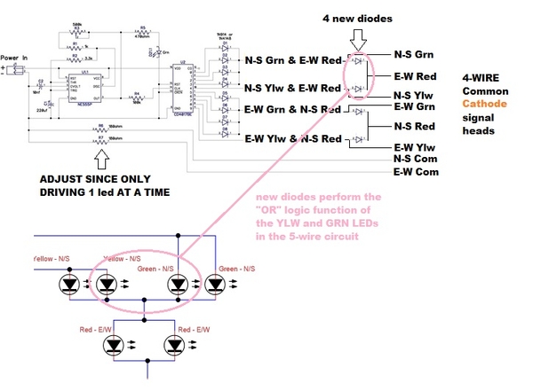
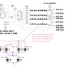
If you want to go the 4-wire method, you could do something like this:
The existing circuit employs a "trick" whereby the YLW or GRN in one direction simultaneously drives the RED in the other direction. This is implemented with the so-called "diode-OR" function which in this case means when either the YLW or GRN LED is on, then the opposite RED is also ON. This is shown in pink above...LEDs being diodes that happen to light up. But this requires the 5-wire implementation. If going to a 4-wire implementation, you must implement this "diode-OR" function independently which in effect means you must add 2 diodes per direction to replace the "OR" function provided by the YLW and GRN LEDs. Of course these diodes are a penny a piece so it's really about the real-estate cost of the PCB than the component cost itself.
There is the separate issue that going to a 4-wire method doubles the current requirement since you can't "double-up" on the LEDs. That is, in the original circuit with the 5-wire LED head, a single 74HC4017 output drives a YLW & RED (in series) or a YLW & GRN (in series). With a 4-wire LED head, each 74HC4017 output drives a the 2-color combination in parallel. In effect this doubles the current draw on the already stressed 74HC4017.
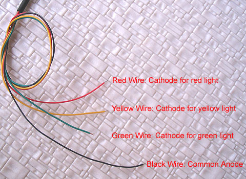
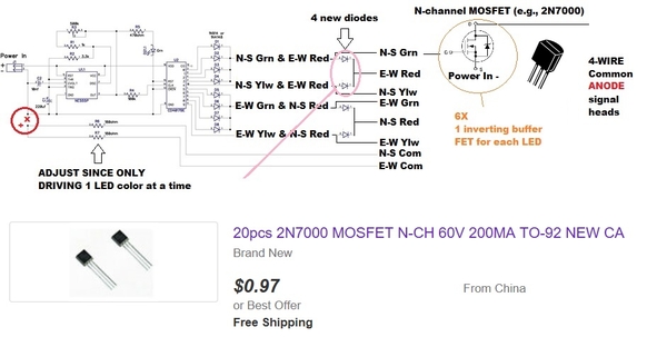
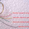
Additionally, from what I can tell, the 4-wire signal heads are typically common-ANODE (common +) whereas the suggested alteration above assume a common-CATHODE (common -). The wehonest 4-wire signal head is common-ANODE.
So by using 6 transistors to flip the polarity of the six LED drive signals, we solve 2 problems. 1) transistor provides adequate current to drive multiple signal heads, and 2) transistor inverts the polarity of each 74HC4017 output so that a common-ANODE signal head can be used. The transistors are 5 cents each...though it does require additional PCB real-estate.


