stan2004 posted:
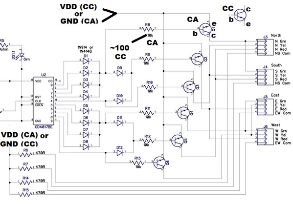
4. But, if this is too dim or you want a dual-purpose (CC or CA) alternative with what I understand is your latest version of the PCB:
a) install the 6 transistors "backwards". That is, rather than CBE for pins 1-2-3, rotate the NPN transistor 180 degrees. The B is still the middle pin but you are swapping the E and B terminals of the transistor. This makes the NPN transistor into a non-inverting buffer using the so-called "emitter follower" configuration. So you get the benefit of additional current driving capability (i.e., the buffering) that a transistor brings to the table.
b) as shown, the 6 transistor emitter at the top which previously went to GND for CA now go to VDD.
c) as shown, the 4 resistors at bottom which previously went to VDD for CA now go to GND.
Note that unless your PCB layout software did something weird, you should be able to cut a single trace for b) and c) and on the bench simply tack the wires to the opposite power supply rail (VDD become GND, GND becomes VDD). Or if re-designing a PCB, you'd make, say, a 3-terminal 0.1" header with the VDD on pin 1 and GND on pin 3. Then use a push-on programming jumper to steer pin 2 to either 1 or 3 depending on the CA vs. CC application.
d) lower the value of the 6 resistors from 10K for CA to, say, 100 ohms for CC.
Ok, I am confused now, self inflicted I'm sure. ![]() The dual purpose idea you have in in 4. and the Note paragraph sounds perfect! I think that is the way to go. I added some pin headers and jumpers to the bread board circuit and was trying to make this work with the mods in b) & c) (along with notes on the modified drawing included). If I am interpreting this correctly, I have b) 3 pin header switching the transistor's emitters between VDD & GND and c) 3 pin header switching between VDD & GND at the Common resistors and another.
The dual purpose idea you have in in 4. and the Note paragraph sounds perfect! I think that is the way to go. I added some pin headers and jumpers to the bread board circuit and was trying to make this work with the mods in b) & c) (along with notes on the modified drawing included). If I am interpreting this correctly, I have b) 3 pin header switching the transistor's emitters between VDD & GND and c) 3 pin header switching between VDD & GND at the Common resistors and another.
I am confused about reversing the transistors, seems like that should be a separate mod (two separate PCBs) and would make using the pin headers kind of difficult, unless that is a permanent reversal for both CA and CC modes? Without reversing the transistors, it's working in the CA mode with headers & jumpers installed, but no luck so far in the CC mode. Going to try it again tomorrow, retracing my wiring mods on the bread board, the BB is getting a bit crowded along with some self induced confusion while making changes.
On the brighter side, no smoke has been released! ![]() Also, the mailman hit the trifecta this afternoon, got MOSFETs, JLC PCBs and We_Honest traffic lights in the mailbox! Been fiddling with all that, which could be adding to my confusion...too much fiddling going on at once.
Also, the mailman hit the trifecta this afternoon, got MOSFETs, JLC PCBs and We_Honest traffic lights in the mailbox! Been fiddling with all that, which could be adding to my confusion...too much fiddling going on at once.


