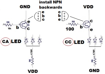
In the original CA (Common Anode) design, as you point out, all the NPN emitters are tied together as a single PCB "net". This so-called net is then hooked to GND. The NPN collectors go to the LEDs..
What I'm suggesting is you simply install the NPN backwards. Now, all the NPN collectors are tied together in a single net. And this net is then hooked to VDD. The NPN emitters go to the LEDs.
The "trick" is you don't have to change the PCB or breadboard wiring to the transistors. You simply rotate the transistors when installing them. Your NPN transistor is of the TO-92 package which has that "D" shaped body which I attempt to show in the diagram.
It sounds like you correctly figured out what I meant by making a pair of 3-pin headers to steer the VDD or GND accordingly. ![]()
To be sure, this is a DIYer's hack. You'd likely get fired if you tried this in a manufacturing company. I figured you had boards made and this would be a way to make them work with either polarity of signal head with only a modest amount of fuss.
As mentioned earlier, do not try this trick with the FETs. There is an analogous idea but it has too many rabbit holes that you can stumble on.


