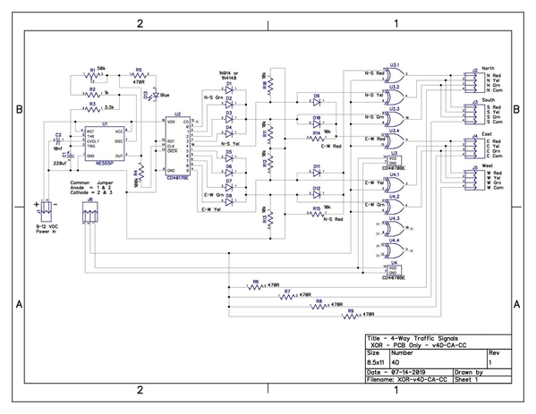
Stan, I finally got a new schematic with revisions for making the traffic signals dual mode (either CA or CC) per your suggestions above. I used the CD4070BE ICs as I have about 10 of those on hand and only a couple of the 74HC86 versions. (In case of unintentional smoke release, I will have sufficient backups on hand with the 4070s.) Still working on the bread board test circuit. I am using individual LEDs and this is taking up a lot of bread board real estate, not to mention jumper wires... I'm thinking that using the actual traffic signals might have been a better way to try this, but I didn't want to damage tany of the actual signals if there are schematic or wiring errors (individual LEDs are much more expendable for testing).
Here's a picture of how it ended up, hopefully it is correct, or at least pretty close. Comments wanted please!
If this passes the once over test, I think I'll order 5 more PCBs for testing. Also gives me more practice in creating PCBs and 5 PCBs for $2 (plus $5.50 shipping) is definitely reasonable for learning.
If this is successful, I think next up will be the PIC chip GRJ suggested above to see how that goes. I am also imagining a PCB for that setup too, which should be another good learning experience. As another plus here, I'll be helping Digikey and JLCPCB keep their doors open. ![]()


